background image


1/153 22-FGC 101 0239/2 Uen  Rev J   

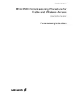
EDA 2530 Commissioning Procedure for

Cable and Wireless Access

EDA 2530 R4.21 GA EC2

Commissioning Instructions


Summary of Contents for EDA 2530

Page 1: ...1 153 22 FGC 101 0239 2 Uen Rev J EDA 2530 Commissioning Procedure for Cable and Wireless Access EDA 2530 R4 21 GA EC2 Commissioning Instructions...

Page 2: ...om disclosure and dissemination to third parties Disclosure and disseminations to the receiver s employees shall only be made on a strict need to know basis The information in this work is subject to...

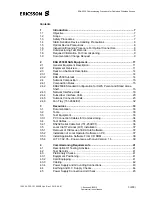
Page 3: ...iguration for CWA Parent and Stand Alone Shelf 16 2 4 3 Network Interface Units 18 2 4 4 Subscriber Interface Units 20 2 4 5 Subrack Connection Units 23 2 4 6 Fan Tray 151 2984 02 32 3 Resources 33 3...

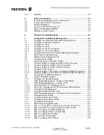
Page 4: ...HDSL Cards If required 83 7 7 3 Create S VLANs for POTS Cards If required 85 7 7 4 Complete VLAN Creation 88 7 7 5 Create S VLANs on the Parent to Subtend Child 2 If required 88 7 7 6 Create S VLANs o...

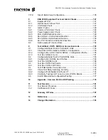
Page 5: ...Connection Units 153 9 1 Configure Activate Test 64 Port Adsl2 Units 153 9 1 1 Check 64 x ADSL Cards for ADSL2 Configuration 153 9 1 2 Configure 64 x ADSL Card for ADSL2 Configuration Profile 155 9 1...

Page 6: ...mmissioning Procedure for Cable and Wireless Access 1 153 22 FGC 101 0239 2 Uen Rev J 2010 04 01 Ericsson AB 2010 Commercial in confidence 6 200 This page intentionally blank to facilitate double side...

Page 7: ...P Card will be configured for H 248 protocol The ADSL2 POTS VoIP Cards and 32 x SHDSL Cards VLANs will be routed to the GigaBit Ethernet Port of the EDA 2530 CP IP Card The Common Part Backhaul GigaBi...

Page 8: ...ing Procedure For Optical Connectors All optical fibre connectors will require inspection for damage and cleanliness 1 7 Commissioning Test Records The commissioning test records at the end of this do...

Page 9: ...ress of the NTP Server e If available fibre loss figures for the sub network under test f The SID document which specifies Configuration information i e Site location Floor Plan Rack Layout Fuse alloc...

Page 10: ...sioning Procedure for Cable and Wireless Access 1 153 22 FGC 101 0239 2 Uen Rev J 2010 04 01 Ericsson AB 2010 Commercial in confidence 10 200 This page is left intentionally blank to facilitate double...

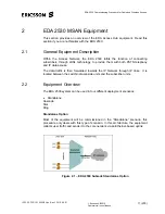
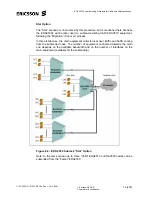
Page 11: ...ology to provide them with both PSTN telephony and IP data access The data traffic is then forwarded towards the IP Network through IP links It is located between the switch network side units and the...

Page 12: ...ng C W EDA2510 equipment following the Migration Cut over process In this architecture the main equipment collects local user traffic and traffic coming from the subtended ones The number of equipment...

Page 13: ...W Release 4 21 32 x VDSL2 64 x ADSL2 interface 64 x POTS VoIP interface Management through Local Terminal LCT via TCP IP 802 3 CP Eth port Out Band Management Used for on site commissioning Managemen...

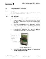
Page 14: ...rt Electronic Part composed of 22 slots housing the electronic units Network Interface Common Parts units and Subscriber Interface channel units b The top part Connection Part comprising the 22 slots...

Page 15: ...erally when one electronic unit is inserted in the subrack one Connection Unit is required in the upper part of the subrack directly above it with the exception of the Common Part unit The type of con...

Page 16: ...e existing configuration The 64 x ADSL2 units are inserted in even numbered slots from slot 2 up to slot 18 in increasing order towards the right The 64 x POTS VoIP units are inserted in odd numbered...

Page 17: ...locks and HDF to MDF cabling are provided by BT HANDIN cabling from HDF blocks designated LLUT or LLUX allows connection to C W subscribers via the BT last mile copper connection Broadband traffic is...

Page 18: ...SP protection the optic fibre cables Tx and Rx will need to be manually disconnected from the Worker unit slot 1 and re connected to the Protection unit slot 22 When replacing the optical fibres to th...

Page 19: ...and for LCT use during commissioning Cabling Note The Ethernet port can use standard Cat 5 screened cable Common Code 1301042 0019 with standard RJ45 connector 5102169 Serial Interface Port This RS 2...

Page 20: ...ith up to a maximum of ten cards providing a maximum of 640 lines Each 64 x ADSL2 card requires its relevant Connection Unit to be fitted above the 64 x ADSL2 card This unit can provide ADSL and ADSL2...

Page 21: ...ion Unit to be fitted above the 64 x POTS VoIP card Note When the combination of 64 x ADSL2 and 64 x POTS VoIP Units are used the Connection Unit required is the 64 x COMBI I F IN Out POTS TAM ETSI Co...

Page 22: ...iding a maximum of 64 lines Each 32 x SHDSL card requires its relevant Connection Unit 02HAT00136AAR to be fitted above the 32 x SHDSL card Figure 2 8 32 x SHDSL Unit Front Panel The functions of the...

Page 23: ...sation This unit is inserted in slot 22 in the upper shelf of the subrack Figure 2 9 Power Supply Connection and Alarm Unit 151 2975 53 Table 2 1 Power Connector Pinout for Power Supply Connection Ala...

Page 24: ...4 Not used PIO1 5 Incoming ground contact nr 1 PIO3 6 Incoming ground contact nr 3 PIO5 7 Incoming ground contact nr 5 PIO4 8 Incoming ground contact nr 4 PIO8 9 Incoming ground contact nr 8 PIO6 10 I...

Page 25: ...Q 128 Pin DIN Connector From UNIT Front 02HAT00282AAQ 64 x COMBI I F I O POTS TAM ETSI LINE 1 64 POTS 1 64 LINE TEST ACCESS 32d 1d 1a 32a TOP If the POTS connectors are cabled to the existing POTS exc...

Page 26: ...a 16a Line 40 a b 15c 16c Line 9 a b 17a 18a Line 41 a b 17c 18c Line 10 a b 19a 20a Line 42 a b 19c 20c Line 11 a b 21a 22a Line 43 a b 21c 22c Line 12 a b 23a 24a Line 44 a b 23c 24c Line 13 a b 25a...

Page 27: ...missioning Procedure for Cable and Wireless Access 1 153 22 FGC 101 0239 2 Uen Rev J 2010 04 01 Ericsson AB 2010 Commercial in confidence 27 200 Figure 2 11 64 Pair COMBO Card to HDF Cable Assembly RP...

Page 28: ...missioning Procedure for Cable and Wireless Access 1 153 22 FGC 101 0239 2 Uen Rev J 2010 04 01 Ericsson AB 2010 Commercial in confidence 28 200 Figure 2 12 64 Pair COMBO to HDF Cable Wiring Diagram R...

Page 29: ...two EDA shelf site connect RJ45 to RJ45 cable from the upper LTA socket on slot 20 and 21 unit on the fully equipped Lower shelf to the upper LTA socket on slot 2 and 3 unit on the Upper shelf On the...

Page 30: ...136 AAR This unit is a Connection Unit for the 32 x SHDSL line units and is located in the connection part slot above the 32 x SHDSL unit It also provides Line Test Access connections for connection t...

Page 31: ...b 12 44 6 Line 13 a b 13 45 Line 13 a b 13 45 Interface Line 14 a b 14 46 Line 14 a b 14 46 7 Line 15 a b 15 47 Line 15 a b 15 47 Interface Line 16 a b 16 48 Line 16 a b 16 48 8 Line 17 a b 17 49 Line...

Page 32: ...is air circulation inside the subrack electronic part by regulating fan speed as a function of temperature In the event of failure of one fan the remaining ones increase their speed to the maximum va...

Page 33: ...release of the EDA 2530 being commissioned 1 3 Customer specific Configuration information i e Floor Plan EDA 2530 Rack Layout EDA 2530 Subrack equipment allocations Cable Running Out Lists 1 3 2 Too...

Page 34: ...xxxx xx xx xx 1 3 RJ45 Crossover cable for connecting the Local Controller Ethernet Port to the EDA 2530 Refer to Section 3 3 1 Q4273 1 4 RS232 Serial Cable Set used to connect the Common Part Unit CP...

Page 35: ...ables 75 terminated with 2 x 1 0 2 3 BT Type 54 connectors Q4272 2 3 DDF Loop Back Cables terminated with 2 x Type 43 connectors 1HAM 10656 ABT or Q4232A 32 4 xDSL line cable Terminated with RJ12 conn...

Page 36: ...fore connecting the RJ12 connector to the Common Part You must disconnect the RJ12 connector from the Common Part before connecting or disconnecting any 9 Way connector to the PC The operator must NOT...

Page 37: ...lled by this setup procedure use the Start Settings Control Panel Add Remove Program utility in the Control Panel to remove the AXH Local Terminal xx yy zz software c To remove the EDA Local Craft Ter...

Page 38: ...windows i586 p exe file in the Java folder CXC_172_4901_R2A_01 on the CD ROM drive to install it Follow the setup wizard to complete the installation confirming the default selections when in doubt d...

Page 39: ...onal Mapping file Columbia will be selected instead of the United Kingdom k The LCT installation is now complete 3 5 4 LCT 07 02 05 Known Issue with Java Version 1 6 LCT 07 02 05 has a known issue wit...

Page 40: ...Commercial in confidence 40 200 g After the computer has restarted install the LCT 07 02 05 EC1 correction patch Copy the patch file p_XdslLineCF tcl from the LCT 07 02 06 GA EC1 Patch folder on the L...

Page 41: ...If the Customer s representative is not present on site enter N A Not Available for the Customer representative 4 3 Preliminary Checks 4 3 1 Equipment Positioning Check the equipment positioning corre...

Page 42: ...ng Check that the positions of service or signal cable terminations on electrical and optical distribution frames or on other equipment comply with the Site Implementation Plan Check that the 64 pair...

Page 43: ...ery 2 5 B1 Negative Voltage of Battery 1 5 B2 Negative Voltage of Battery 2 Note The 5 Pin D Type Connector on the Power Cable is Female Figure 4 1 Power Supply Connection Unit 151 2975 53 Pin Allocat...

Page 44: ...inet These two 16 Amp MCB s are connected to Socket Vb1 on the Power Supply Connection Unit 151 2975 53 in slot 22 The main 50v supply Supply 2 is connected to two Single Pole 16 Amp Miniature Circuit...

Page 45: ...witch OFF MCB 3 and check the 50 volts is removed Switch ON Circuit Breaker MCB 4 at the top of the EDA 2530 cabinet Check for 50 volts on Pin 5 of the D Type connector for Socket Vb2 Switch OFF MCB 4...

Page 46: ...sioning Procedure for Cable and Wireless Access 1 153 22 FGC 101 0239 2 Uen Rev J 2010 04 01 Ericsson AB 2010 Commercial in confidence 46 200 This page is left intentionally blank to facilitate double...

Page 47: ...etwork Address range as the Out of Band Management IP Address of the EDA 2530 Note For Windows 2000 OS use step a for Windows XP use step b and for Vista OS use step c all other steps are common to Wi...

Page 48: ...IP Address is 150 150 150 16 Set the Laptop IP Address to 150 150 150 16 Note The EDA 2530 IP Address is 150 150 150 4 i In the Subnet Mask field enter the subnet mask for the EDA 2530 node This will...

Page 49: ...es and applications Services Right click on Symantec Management Client and select Stop Right click on Symantec Endpoint Protection and select Stop Now close all open windows n Start the Command prompt...

Page 50: ...top Bit 1 Parity None Flow control XON XOFF PC to be installed with EDA2530 LCT application version 07 02 04 RS232 serial lead type 151 2502 01 to connect between the PC serial port or USB and the CP...

Page 51: ...elay saveenv return printenv return to print display settings i Remove the CP card from slot 1 j Replace the Compact Flash card k Reinsert the CP card into slot 1 with the CF card fitted l At the seco...

Page 52: ...that _UP ID file is present s At the command prompt type the following mv space _UP ID space UP ID return ls space l t Check that UP ID file is present must be upper case u At the command prompt type...

Page 53: ...n s Refer to the Site Installation Documentation pack These units are inserted in odd numbered slots starting from slot 3 up to slot 19 in increasing order towards the RHS Note If a 64x POTS VoIP unit...

Page 54: ...Start All Programs AXH EDA Local Terminal xx yy zz AXH EDA Local Terminal Or select the AXH EDA Local Terminal shortcut from the desktop A window with Starting Local Terminal Please wait will be disp...

Page 55: ...net Browser b Ensure the proxy server settings are disabled as follows From the browser top line menu select Tools Connections tab LAN settings from the LAN settings window ensure that all options are...

Page 56: ...altered from the default of 150 150 150 4 to allow for multiple EDA s on each site The address must be modified in line with the following table DLE ID IP Address DLE ID IP Address DLE ID IP Address 0...

Page 57: ...d the CP card will reboot o Wait around 5 min before attempting to login again this time using the new OBM IP address 5 6 Software Inventory Check Check the Software Inventory on each 64 x ADSL2 card...

Page 58: ...ow e Right click and hold over the 64x ADSL2 card to be checked Select HW SW Inventory from the menu f In the window displayed check that the Running Bank Yes contains the correct software release Thi...

Page 59: ...ontains the correct software release This is just an example screen k Click on Close to close the Inventory window l Check the H W and S W Inventory for all new 64x POTS VoIP cards and confirm that th...

Page 60: ...w 32 x SHDSL cards and confirm that they have the correct H W and S W release q If the unit s Software releases do not correspond with the releases listed in the R4 21 Software table at the beginning...

Page 61: ...R4 21 GA EC2 software files onto the LCT PC hard drive at location C Mv36bLT tftp R4 21_GA_EC2 b From the Windows Start menu run the TFTP Server application select path Start All Programs AXH EDA Loc...

Page 62: ...ill be displayed g Double click on the tftp directory then on the R4 21_GA_EC2 directory to list the configuration files which have been stored at this location h The SwDownload sdc configuration file...

Page 63: ..._172_3777_R2B27 tftp s38 1st field is the unit type 2nd field is the software serial code and the software version 3rd field is the file name j Select the SwDownload sdc configuration file then OK now...

Page 64: ...load is successful follow step o to perform the Bank Switch Otherwise go to step q or r as appropriate for the download result p Download successful After a successful software download press the Swit...

Page 65: ...was unsuccessful the Download Failed label will be visible The System Software Download Status window will display the problems encountered during the software download Close the windows and go back...

Page 66: ...g one a forced switch MUST NOT be performed from the LCT If it is selected the configuration database will be corrupted and the CP card won t reboot If the result following download to the CP card is...

Page 67: ...LE ID eg EANCN0102 Norwich North this is site specific Specified in site SID document OOB IP Address Out Of Band 150 150 150 x Where x 4 default to 15 Out Of Band IP Address is determined by the DLE I...

Page 68: ...ew Cross This is site specific and will be supplied by C W Usually the same value as used by the EDA2510 Primary Media Gateway Controller Domain name Primary Media Gateway Controller Domain name eg iM...

Page 69: ...be used by the Parent to subtend the Child 1 an EDA 2510 node Note4 CP Port SFP3 when fitted will be used by the Parent to subtend the Child 2 an EDA 2530 node Note5 CP Port SFP4 when fitted will be u...

Page 70: ...d an existing EDA 2510 then the backhaul SFP1 module won t be available at this Commissioning stage will be available when the two node types are migrated Even though SFP1 is not physically present co...

Page 71: ...d corner to modify the configuration g Select Refresh then Close to return to the CP IP SFP Port Provisioning screen h If the SFP2 SFP3 SFP4 module s have not configured correctly then repeat the abov...

Page 72: ...Port 1 GigE interface to be the In Band Management interface a Right click on the CP Card and select Ethernet Lines from the sub menu b Select the Port 1 button then click on Configure the following w...

Page 73: ...low steps d to f of Section 7 2 1 above to configure CP Port 2 Do NOT select the Local In Band Mng option this is required for CP Port 1 only b Select Close to return to the main LCT screen 7 2 3 Conf...

Page 74: ...he top line menu select the path Configuration IP Ethernet Management Bridging Parameters b From the Equipment Level Bridging Parameters Configuration window change the Bridge Ethertype S hex str fiel...

Page 75: ...PVC Config Child 1 adsl e42 10 files 1 per even slot for all sites PVC Config Child 2 adsl e42 10 files 1 per even slot for all sites PVC Config Child 3 adsl e42 10 files 1 per even slot for all site...

Page 76: ...ile Name File Type File Quantity SHDSL Line Profiles lcp 1 for all sites Standard SHDSL Stack Profiles psp 1 for all sites Standard Static VLAN Management Ports fixed nsvm 1 for all sites Standard Sta...

Page 77: ...ct Replicate cell all entries in the Ne Name column will now be set to the required OOB IP Address e In the S VLAN ID column the template will load the default value of 22 check with the CWA DLE plann...

Page 78: ...cess 1 153 22 FGC 101 0239 2 Uen Rev J 2010 04 01 Ericsson AB 2010 Commercial in confidence 78 200 h Select Read Network near the top of the screen this will confirm the configuration if there are any...

Page 79: ...ner The Define VLAN user port membership screen will be displayed b Select File then Open then navigate to the relevant folder and select the template file Static VLAN Management Ports fixed nsvm Sele...

Page 80: ...ress b In the S VLAN ID column the three Data Inband entries will be loaded with the default value of 22 check with the CWA DLE planning document what the S VLAN ID value should be set to for the node...

Page 81: ...Create S VLANs for Additional ADSL Cards If required The template file creates the VLAN data for the ADSL slot 2 card only additional S VLANs must be created for other ADSL cards in the DATA_INBAND n...

Page 82: ...table This is done by holding down the ctrl key then click on all even numbered intlag interface entries in turn until all ADSL card entries have been highlighted ie intLag 1 2 for slot 2 ADSL card i...

Page 83: ...d display OK g Select Read Network near the top of the screen this will confirm the configuration if there are any incorrect entries they will be highlighted at this point 7 7 2 Create S VLANs for SHD...

Page 84: ...For each SHDSL card s the relevant SHDSL slot numbered intLag entries need to be selected in the table This is done by holding down the ctrl key then click on each new SHDSL slot numbered intLag inter...

Page 85: ...wn list All new entries in the Command column will now be set to addPort f Select Apply All from the bottom LHS of the screen The rows will turn Green and under the Result column the field should disp...

Page 86: ...2 7 153 VOIP_GW3 9 154 VOIP_GW4 11 155 VOIP_GW5 13 156 VOIP_GW6 15 157 VOIP_GW7 17 158 VOIP_GW8 19 159 VOIP_GW9 21 160 VOIP_GW10 b In the VLAN Egress Ports entry x window select Read NE Then select in...

Page 87: ...ommand column will now be set to addPort f Select Apply All from the bottom LHS of the screen The rows will turn Green and under the Result column the field should display OK g Select Read Network nea...

Page 88: ...o Subtend Child 2 If required Note This sub section is only to be applied to the Parent EDA 2530 that is subtending a Child 2 EDA 2530 The last screen in the previous sub section shows the Parent EDA...

Page 89: ...es button the display will then revert back to the main Static VLAN table e Against the highlighted ethG 1 1 3 entry in the table under the Command column right click to select addPort from the drop d...

Page 90: ...dence 90 200 7 7 5 2 Create VIDEO S VLAN a Against the VIDEO S VLAN Name double left click on the ethG 1 1 2 entry under the User Port Interface Name column b In the VLAN Egress Ports window select Re...

Page 91: ...o select addPort from the drop down list of options f Select Apply All to add the new entry g Select Read Network to confirm the updated configuration the following screen shows the newly created VIDE...

Page 92: ...ew entry g Select Read Network to confirm the updated configuration the following screen shows the newly created VOIP_GW1 ethG 1 1 3 entry h Repeat steps a to g to add the VOIP_GW2 S VLAN Name entry f...

Page 93: ...table l Repeat steps a to g to add the VOIP_GW8 S VLAN Name entry for ethG 1 1 3 in the Static VLAN table m Repeat steps a to g to add the VOIP_GW9 S VLAN Name entry for ethG 1 1 3 in the Static VLAN...

Page 94: ...ic between the Parent EDA2530 subtended Child 2 EDA2530 7 7 6 Create S VLANs on the Parent to Subtend Child 3 If required Note This sub section is only to be applied to the Parent EDA 2530 that is sub...

Page 95: ...ev J 2010 04 01 Ericsson AB 2010 Commercial in confidence 95 200 VOIP_GW9 VOIP_GW10 a Follow sub section 7 7 5 1 to 7 7 5 3 to create 12x new ethG 1 1 4 entries in order to set up the paths for In Ban...

Page 96: ...n created it is necessary to build an interface in that VLAN to which an IP address can be assigned This is done by performing the following steps a From the main LCT screen select the path Configurat...

Page 97: ...he type of EDA 2530 refer to the table below C VID ID EDA 2530 3200 Parent 200 Child 1 1200 Child 2 2200 Child 3 e In the S VLAN ID field enter the VLAN number to be used for In Band management Check...

Page 98: ...on the Details button the window will be expanded to display Interface Data c In the L2 Interface Name field select vlanCVID SVID from the drop down list Now modify this field to enter the CVID and SV...

Page 99: ...DLE planning document f Click on the Local In Band Mng checkbox to specify this IP configuration as the IBM IP configuration g In the MTU Size bytes field enter 1500 The number of bytes for the larges...

Page 100: ...in the first line then highlight it and select Delete to remove it c Highlight the empty first row of the table and click on the Details button the window will be expanded to display Routing Details d...

Page 101: ...10 Commercial in confidence 101 200 7 11 xDSL Bridge Management Configure xDSL Bridge a From the LCT main screen select the path Configuration IP Ethernet Management Browse Configure xDSL Bridge The x...

Page 102: ...5 Change the address if necessary in this column for all entries as follows Change the 1st entry in this column to the correct IP address select the 1st entry then left click the 1st entry drag down...

Page 103: ...y option Select the 1st entry then left click drag down to the bottom of the column to highlight all entries Right click select Replicate cell all entries in the Command column should now be set to mo...

Page 104: ...ild 3 EDA2530 c Select the appropriate file for the specific ADSL slot position Slot 2 file xDSL Bridge Management PVC Management Slot 2 e42 Slot 4 file xDSL Bridge Management PVC Management Slot 4 e4...

Page 105: ...and Wireless Access 1 153 22 FGC 101 0239 2 Uen Rev J 2010 04 01 Ericsson AB 2010 Commercial in confidence 105 200 7 12 2 Check PVC Management PPPoA Payload MRU Settings a Select the DHCP PPPoX AGENTS...

Page 106: ...gure PVC Management a Select the CONTROL tab b In the Access Node column the template will load the default OOB IP address of 150 150 150 4 the Node being commissioned is likely to have a different on...

Page 107: ...value select the 1st entry left click drag down to the bottom of the column to highlight all entries Right click select Replicate cell all entries in this column will now be set to the required value...

Page 108: ...4 3264 3328 3392 3456 3520 3584 3648 3712 3776 3840 CHILD 1 EDA 2530 C VLAN Id for ADSL Port ADSL1 slot2 ADSL2 slot4 ADSL3 slot6 ADSL4 slot8 ADSL5 slot10 ADSL6 slot12 ADSL7 slot14 ADSL8 slot16 ADSL9 s...

Page 109: ...VLAN ID s for ADSL cards PARENT EDA 2530 CHILD 1 EDA 2530 SHDSL No 3 4 1 2 3 4 1 2 Port Slot Slot 18 Slot 19 Slot 20 Slot 21 Slot 18 Slot 19 Slot 20 Slot 21 1 3713 3745 3777 3809 713 745 777 809 32 3...

Page 110: ...DSL entry in this column then right click select the copy option Left click on the next entry drag down to the bottom of the column to highlight all the other entries Right click select Paste incremen...

Page 111: ...10 Commercial in confidence 111 200 7 12 4 Configure Additional xDSL Cards a If other ADSL or SHDSL cards are to be configured then repeat Sections 7 12 1 7 12 2 7 12 3 above for each additional card...

Page 112: ...4 dfc Slot 6 file xDSL Bridge Management Downstream Flows Slot 6 dfc Slot 8 file xDSL Bridge Management Downstream Flows Slot 8 dfc Slot 10 file xDSL Bridge Management Downstream Flows Slot 10 dfc Slo...

Page 113: ...OOB IP Address d In the Command column set all entries to modify as follows Double click on the 1st entry in this column and from the drop down list select the modify option Select the 1st entry then...

Page 114: ...en then the following screen will be displayed which will default to the Channel tab c In the Ne Name column the template will load the default OOB IP address of 150 150 150 4 the Node being commissio...

Page 115: ...the create option Select the 1st entry then left click drag down to the bottom of the column to highlight all entries Right click select Replicate cell all entries in this column should now be set to...

Page 116: ...lready configured in the EDA2530 then click the Read Network button to view and check the SHDSL Line Profiles If the profiles are correct this sub section is not required If the profiles are not corre...

Page 117: ...the required OOB IP Address d In the Command column in the 1st entry double click the empty field and select the create option from the drop down list Select the 1st entry left click drag down to the...

Page 118: ...own The above tables show a typical example of SHDSL Line Profiles Actual required SHDSL Line profiles should be supplied by the Customer 7 16 Configure SHDSL Stack Profiles Note This section ONLY app...

Page 119: ...n left click the 1st entry drag down to the bottom of the column to highlight all entries Right click select Replicate cell all entries in the Ne Name column will now be set to the required OOB IP Add...

Page 120: ...04 01 Ericsson AB 2010 Commercial in confidence 120 200 Profile Name Profile Service SHDSL TC Layer ATM ipdslamAtmShdsl atmByteAligned EFM ipdslamEthernetShdsl Efm6465 The above table shows a typical...

Page 121: ...ric POTS RTP Profiles rtp 1 for all sites POTS ToIP Profile File no longer required tip 1 for all sites Standard National Mapping file gz 1 for all sites Standard 7 17 2 Step 1 LCT 07 02 05 Known Issu...

Page 122: ...the UK National Mapping file is stored Which is named as United_Kingdom9 1_NM_United_Kingdom2 1_CC tar gz Note If the browse button is not available this may be because the wrong version of Java is l...

Page 123: ...esn t then repeat the process and Apply Configuration again until it does l The POTS card s will go offline and reboot be patient and wait for them to initialise which will take approximately 2 min Th...

Page 124: ...screen select the path Configuration Connection Modules b On the Connection Modules configuration screen wait for the information to be read into the table c Highlight the 1st Connection Module for th...

Page 125: ...orts 1 to 64 To do this quickly then First select Port 1 box and untick it press and hold down the shift button and select the Port 64 box All 64 ports should now be unticked ie disabled h Click on th...

Page 126: ...c POTS RTP Profiles rtp Select Open then the RTP Profiles table will be filled in and the following screen will be displayed NOTE Each potential POTS cards must have its own RTP profile configured One...

Page 127: ...fault GW addresses for all ten POTS cards slots 3 to 21 Even if only one POTS card is physically installed Explanation The Def GW IP Addresses are determined from the POTS cards IP Addresses if the PO...

Page 128: ...option Select the 1st entry then left click drag down to the bottom of the column to highlight all entries Right click select Replicate cell all entries in this column should now be set to create h Se...

Page 129: ...EDA 2530 Commissioning Procedure for Cable and Wireless Access 1 153 22 FGC 101 0239 2 Uen Rev J 2010 04 01 Ericsson AB 2010 Commercial in confidence 129 200...

Page 130: ...17 7 Step 6 Check TOIP Profiles a Whilst still in the RTP Pots Profiles Management screen from the previous section select the POTS ToIP Profile button at the top of the screen b Select Read Network...

Page 131: ...he list of options In the new window click on Configure to view the current port configurations The POTSx64 Lines Configuration screen for Line 1 will be displayed b In the AC profile field select fro...

Page 132: ...P Local IP Address field enter the appropriate IP Address for the relevant POTS card slot position This address is unique for the slot position and is also site specific Refer to the CWA Voice Card De...

Page 133: ...ion button at the bottom of the window to change the profiles of all 64 ports This may take up to 1 min m Select the Status Maintenance tab ensure all ports are still selected ie they are all red Now...

Page 134: ...ss 1 153 22 FGC 101 0239 2 Uen Rev J 2010 04 01 Ericsson AB 2010 Commercial in confidence 134 200 o Select the Close button to exit the window to return to the main LCT screen p Repeat steps a to o fo...

Page 135: ...configured a From the main LCT screen select Configuration VoIP Management VoIP Global Parameters The VoIP Global Parameters window will be displayed b Change the H248 Protocol field from centralised...

Page 136: ...8 Virtual Gateway table will be filled in with information for all 10 POTS card positions as shown in the following screen h The displayed screen will default to the Gateway 1 tab Note The Generic H24...

Page 137: ...and select Delete Rows from the menu Click Yes to confirm i e To delete the row for unequipped POTS card in slot 21 click on row 10 Identifier 10 k Repeat the above step to delete all other unwanted...

Page 138: ...identifier e g 0203 SLOT Slot the POTS card is installed in for this gateway n The Signalling Gateway IP Address field must be entered This address is unique for each POTS line card for the slot posit...

Page 139: ...ng Procedure for Cable and Wireless Access 1 153 22 FGC 101 0239 2 Uen Rev J 2010 04 01 Ericsson AB 2010 Commercial in confidence 139 200 q The Gateway 2 and Gateway 3 tabs remain the same for all sit...

Page 140: ...s Media Gateway Controller for the site Refer to the MGWC IP Address column on the CWA Voice Card Deployment spreadsheet for the site being commissioned IMPORTANT Be very careful as the same MGWC IP A...

Page 141: ...down list Repeat for the next entry in the column if applicable there will be a maximum of 10 entries one for each installed POTS card y Select Apply All and the Result column should display OK again...

Page 142: ...Terminations Slot x trm file required for the specific POTS card slot position The options are Generic H248 Terminations Slot 3 trm Generic H248 Terminations Slot 5 trm Generic H248 Terminations Slot...

Page 143: ...s is unique for each POTS line card for the slot position and is also site specific This is specified in the CWA Voice Card Deployment spreadsheet Change the 1st entry in this column to the unique IP...

Page 144: ...should turn green s Check there are 64 entries for each POTS card t Now select Read Network u When all entries have been stored refer back to the Termination tab and the admin status for all entries s...

Page 145: ...Read Network g Check the Admin Status column shows inService for each POTS card h Check the Oper Status column shows restarting for each POTS card Note The Oper Status column displays restarting unti...

Page 146: ...ioning Procedure for Cable and Wireless Access 1 153 22 FGC 101 0239 2 Uen Rev J 2010 04 01 Ericsson AB 2010 Commercial in confidence 146 200 This page is left intentionally blank to facilitate double...

Page 147: ...is within limits as specified in the TX Launch Power Limits table below TX LAUNCH POWER LIMITS OPTICAL MODULE INTERFACE MAX LIMIT MIN LIMIT SFP SU57AD 1000BASE SX GbE 850nm Multi Mode 2Km 3 5 dBm 0 4...

Page 148: ...k the Receive from all Cards box Click Apply Settings button and check that there are no active alarms relevant to the electronic units d On the Common Part unit in slot 1 disconnect the loop on SFP P...

Page 149: ...alarm browser d Switch ON the 3rd and 4th Circuit Breakers at the top of the EDA 2530 cabinet This will reconnect power to Socket Vb2 on the Power Supply Connection Unit in slot 22 Check the Green Vb...

Page 150: ...nserted unit is displayed correctly and without alarms Refresh the Alarm Browser check the following alarms disappear on the alarm browser cpEqtCardActualChangedTrap cpReplaceableUnitMissingTrap c Rep...

Page 151: ...lays the extracted unit Check the following alarms appear on the alarm browser cpEqtCardActualChangedTrap cpReplaceableUnitMissingTrap b Insert the previously extracted unit and check that The inserte...

Page 152: ...he path Configuration Equipment Date Time The Equipment Date And Time screen is displayed b In the Equipment Date And Time area set the current date in the Date mm dd yyyy field using the calendar fun...

Page 153: ...49 to 52 53 to 56 57 to 60 and 61 to 64 One ADSL Line should be tested from each group of four lines This will ensure that each line IC is tested Proceed by configuring all 64 lines then activate All...

Page 154: ...IC Check that only the following three Transmission Mode Type boxes are ticked ADSL 2 G 992 5 over POTS ADSL 2 G 992 3 over POTS ADSL G 992 1 over POTS Note If the Configuration Profile is not set to...

Page 155: ...i When all 64 lines have been checked on the 64 x ADSL card click on the Close button to close the window j Repeat the checks steps a to i for each new 64 x ADSL Card k If any incorrectly configured...

Page 156: ...d read the display Any enabled lines will have to be disabled manually 9 1 2 2 Configure ADSL Lines a Place the cursor on the 64 x ADSL unit to be configured b Right click on the unit and select Lines...

Page 157: ...ne 1 h Click on the Line Configuration Profile drop down menu arrow and select ADSL2plus_SLOW_BASIC i Important Ensure that only the following three Transmission Mode Type boxes are ticked ADSL 2 G 99...

Page 158: ...wait message disappears n Click on the first ADSL Line configured o Wait until the Address shows Slot as selected Card Type ADSLx64 Line as selected then check that the Configuration Profile is set t...

Page 159: ...Enable radio button d Click on the GO button Wait for all 64 lines to be enabled e Check the result is Found Configured 64 Updated 64 Failed 00 If there are any failures click on the View Error Log bu...

Page 160: ...m the menu c When the ADSL x 64 Lines window appears click on the ADSL Line to be enabled or disabled then left click on the Configure button d Click on the Status tab e If the Disable button is greye...

Page 161: ...Configured and Activated and can therefore be tested by being connected to an xDSL modem at the HDF a Connect the xDSL modem or Golden Modem to the relevant pair of wires on the HDF Handin Frame LLUT...

Page 162: ...the Alarm browser i Power up the xDSL modem or Golden Modem or Tester and check that the Loss of Power or Loss of Signal alarm for the selected line disappears from the alarm browser j Disconnect the...

Page 163: ...to 20 21 to 24 25 to 28 and 29 to 32 All SHDSL Lines should be tested from each group of four lines This will ensure that each line IC is tested Proceed by configuring all 32 lines then activate All s...

Page 164: ...ed 00 If there are any failures click on the View Error Log button and read the display Any enabled lines will have to be disabled manually 9 2 1 2 Configure SHDSL Lines a Place the cursor on the 32 x...

Page 165: ...s selected Card Type SHDSLx32 Line as selected g Ensure that SHDSL Line 1 is selected The configuration will default with the Line Configuration Profile not set h Click on the Line Configuration Profi...

Page 166: ...l the Address shows Slot as selected Card Type SHDSLx32 Line as selected then check that the Configuration Profile is set to SHDSL Profile 1 o Click on the next SHDSL Line to be checked p Repeat steps...

Page 167: ...read the display Any disabled lines will have to be enabled manually f Select the Check radio button g Click on the GO button Wait for all 32 lines to be checked h Check the result is Found Configured...

Page 168: ...le button to enable the line g The Enable button should now be greyed out and the Disable button should be available h If the Enable button is greyed out this indicates that the line is enabled i Clic...

Page 169: ...ock b Wait for activation of the SHDSL line indicated by the modem s WAN LED turning ON and the SHDSL line turns from yellow to green For Golden Modem Tester wait for Training followed by Showtime to...

Page 170: ...Loss of Signal or Loss of Synch Word alarm for the selected line disappears from the Alarm browser l Repeat steps a to k for the other lines to be tested each time moving the SHDSL modem Tester to th...

Page 171: ...HDF Handover Frame LLUL block and check for an earth condition b Connect a digital multimeter to the Ve B leg of the first POTS line on the HDF Handover Frame LLUL block the measurement should be nomi...

Page 172: ...the Common Part in slot 1 If you have disconnected it refer to Section 5 4 to reconnect the LCT and Log On to EDA 2530 again 9 4 1 Check Test Relay Switching Correctly This test must be performed on t...

Page 173: ...ard Test f Click on the Refresh button the radio buttons will be unselected g In the TAM Connection Module section select Normal Operation radio button then click on the Apply button Click on Yes on t...

Page 174: ...L card or between line 17 to Line 32 for an SHDSL card and repeat the test steps d to o to perform an Inward and Outward test on the 2nd line selected q When two lines have been tested on the 64 x ADS...

Page 175: ...282AAQ cm adslpotsx64 TAM PPB 32 x TAM 02HAT00136AAR cm x32 TAM Notes The Slot Card shows the Electronic card expected in that slot the card may not be fitted The Connection Module Type Actual shows t...

Page 176: ...check that all of the POTS Pass Back boxes are ticked for all ports 1 to 64 j When the ADSL card is fitted WITH an associated POTS VoIP card check that all of the POTS Pass Back boxes are unticked fo...

Page 177: ...ked to EARTH to ensure no earth faults are present d Repeat steps a to c for all 64 lines on the Connection Unit 02HAT00282AAQ each time moving the multimeter to the next line pair to be tested on the...

Page 178: ...interface can be seen e If the EDA 2530 is to be backhauled directly to the IP network then leave it powered up Then follow the Handover process as detailed in the Migration procedure which is coded a...

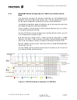
Page 179: ...confidence 179 200 10 Appendix Common Part Unit DIP Setting DIP Switch configuration Common for all 2530 IP Common Part Units SWITCH 1 OFF 2 OFF 3 OFF 4 OFF 5 ON Figure 12 1 Common Part Unit 2530 IP...

Page 180: ...missioning Procedure for Cable and Wireless Access 1 153 22 FGC 101 0239 2 Uen Rev J 2010 04 01 Ericsson AB 2010 Commercial in confidence 180 200 This page intentionally blank to facilitate double sid...

Page 181: ...ON LIMITED CUSTOMER REFERENCE 11 1 Test Record Procedure The results of all tests described in this Commissioning Specification are to be recorded in the accompanying spreadsheet coded as 1 1523 FGC 1...

Page 182: ...UT LLUL and MDF Block details in this table Sub rack Vert A C Sub rack Vert A C 2 1 64 1 64 1 64 4 1 32 65 96 65 96 4 33 64 101 132 101 132 6 1 64 133 196 133 196 8 1 64 201 264 201 264 10 1 32 265 29...

Page 183: ...t Configure PVC satisfactory Y N NA 7 13 xDSL Bridge management Configure Downstream Flow satisfactory Y N NA 7 14 Configure ADSL Profiles satisfactory Y N NA 7 15 Configure SHDSL Line Profiles satisf...

Page 184: ...mmissioning Specification 1 153 22 FGC 101 0239 2 Uen The Customer s representative will complete their Checklist after Migration is complete ERICSSON REPRESENTATIVE NAME ____________________________...

Page 185: ...X 0161 209 2410 E MAIL david saville ericsson com FROM OF ADDRESS TEL FAX E MAIL THE FOLLOWING CHANGE IS SUBMITTED FOR CONSIDERATION DOCUMENT 1 153 22 FGC 101 0239 2 Uen ISSUE SECTION PAGE PARA DETAIL...

Page 186: ...1 153 22 FGC 101 0239 2 Uen Rev J 2010 04 01 Ericsson AB 2010 Commercial in confidence 186 200 DOCUMENT CHANGE REQUEST DOCUMENT 1 153 22 FGC 101 0239 2 Uen ISSUE SECTION PAGE PARA DETAILS OF CHANGE C...

Page 187: ...Access Server CES Circuit Emulation Service s CP Common Part CPE Customer Premises Equipment DDF Digital Distribution Frame DLE Digital Local Exchange Another name for the Access Hub ADSL SHDSL POTS...

Page 188: ...g Tree Protocol SCSI Small Computer System Interface SDH Synchronous Digital Hierarchy SFP Small Form factor Pluggable SHDSL Single pair High speed Digital Subscriber Line 2 3 Mbit s Down 2 3 Mbit s U...

Page 189: ...ioning Procedure for Cable and Wireless Access 1 153 22 FGC 101 0239 2 Uen Rev J 2010 04 01 Ericsson AB 2010 Commercial in confidence 189 200 VPI Virtual Path Identifier xDSL x Digital Subscriber Line...

Page 190: ...issioning Procedure for Cable and Wireless Access 1 153 22 FGC 101 0239 2 Uen Rev J 2010 04 01 Ericsson AB 2010 Commercial in confidence 190 200 This page is intentionally blank to facilitate double s...

Page 191: ...rators Handbook EDA2530 Equipment Handbook 1QDE 10574 AGT YYA Installation Guide for Access Hub and Associated Equipment for Cable and Wireless 04QDE 00077 ABP YYA NxTest Head and NxDSL Commissioning...

Page 192: ...missioning Procedure for Cable and Wireless Access 1 153 22 FGC 101 0239 2 Uen Rev J 2010 04 01 Ericsson AB 2010 Commercial in confidence 192 200 This page intentionally blank to facilitate double sid...

Page 193: ...1 unchanged EDA2530 MSAN Equipment sec 2 unchanged Resources sec 3 unchanged Commissioning requirements sec 4 unchanged Initial Configuration now sec 5 was sec 6 IP Address of PC now sec 5 1 was sec 6...

Page 194: ...the Data VLAN Sec 10 11 Network Integration section and EDA Handover And Acceptance section deleted these are now included in the EDA 2530 Migration procedure Subsequent sections are renumbered PA5 2...

Page 195: ...17 03 2009 Fourth Issue changes to add POTS card configuration Sec 3 5 4 Added a new sub section called LCT 07 02 05 Known Issue with Java Version 1 6 With LCT 07 02 05 there is a known Issue with Ja...

Page 196: ...nly select three Transmission Mode Types these are ADSL2 G 992 5 over POTS ADSL2 G 992 3 over POTS ADSL G 992 1 over POTS All other Transmission Mode Types must be deselected when the ADSL cards are c...

Page 197: ...7 5 4 Added new sub section detailing how to Create S VLANs on the Parent to Subtend Child 2 Sec 7 5 5 Added new sub section detailing how to Create S VLANs on the Parent to Subtend Child 3 Sec 7 6 C...

Page 198: ...s Section 7 17 9 Step 8 H248 Virtual Gateway Configuration revised for Generic H248 VGW Configuration Slots 3 to 21 hvgw files Section 7 17 9 2 H248 Terminations Configuration revised for Generic H248...

Page 199: ...EDA 2530 Commissioning Procedure for Cable and Wireless Access 1 153 22 FGC 101 0239 2 Uen Rev J 2010 04 01 Ericsson AB 2010 Commercial in confidence 199 200 End of section End of Document...

Page 200: ...ing Procedure for Cable and Wireless Access 1 153 22 FGC 101 0239 2 Uen Rev J 2010 04 01 Ericsson AB 2010 Commercial in confidence 200 200 This page has been left intentionally blank to facilitate dou...

Reviews: