EDA 2530 Commissioning Procedure for Cable and Wireless Access
1/153 22-FGC 101 0239/2 Uen Rev J 2010-04-01
©
Ericsson AB 2010
Commercial in confidence
107 (200)
d.
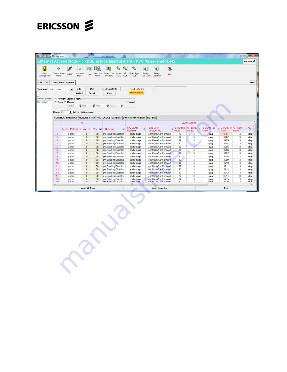
Select the “
Bridge PVC
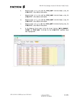
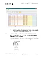
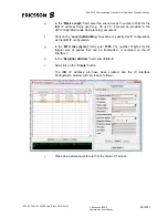
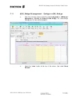
” tab, the following screen will be displayed:-
e.
In the “
S-VLAN id (outer)”
column the template will load the default value
of 22, check with the CWA planning document what the S-VLAN ID value
should be set to for the node being commissioned. This value will be either
21 or 22.
In the “
S-VLAN ID”
column change if necessary the value of each entry, to
21 or
22
as appropriate.
Change
the
1
st
entry in this column to the correct “
S-VLAN ID”
value, select
the 1
st
entry, left click & drag down to the bottom of the column to highlight
all entries. Right click & select “
Replicate cell
”, all entries in this column will
now be set to the required value.
f.
In the “
C-VLAN id (inner)
” column, the 1
st
entry is for Port 1 of ADSL1 slot
2 and increments in order down to Port 64. If ADSL2 slot 4 card is fitted the
65
th
entry is for Port 1 and the 128
th
entry is for Port 64 for this unit, and so
on. If SHDSL slot 20 card is being fitted the 1
st
SHDSL entry is for SHDSL
Port 1 and the 32
nd
SHDSL entry is for SHDSL Port 32 for this unit, and so
on. The SHDSL card entries will follow on after Port 64 of the last ADSL
card fitted.
Check that the range of “C-VLAN id” values for the relevant xDSL card is
correct, as shown in the appropriate PVC Management table which follow:-

