EDA 2530 Commissioning Procedure for Cable and Wireless Access
1/153 22-FGC 101 0239/2 Uen Rev J 2010-04-01
©
Ericsson AB 2010
Commercial in confidence
14 (200)
2.3
Rack And Subrack Description
2.3.1
Rack
The EDA 2530 equipment is installed in an ETSI type rack with the system alarm
rack lamps being located on the rack top. (If fitted).
2.3.2
EDA 2530 Subrack
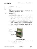
The EDA 2530 subrack comprises 22 slots for the service units and 22 slots for the
interface modules and is divided into three parts:
a.
A bottom part (
Electronic Part
) composed of 22 slots housing the electronic
units – Network Interface Common Parts units and Subscriber Interface
channel units.
b.
The top part (
Connection Part
) comprising the 22 slots for the interface
modules – Power and Alarm Interface (containing the two Power connectors,
the alarm connections and synchronisation connections), and the interface
modules corresponding to the Subscriber Interface units in the Electronic
Part.
c.
Between the subrack top and bottom parts is the fan unit (
FAN
) (151-
2984/02) optimising the air forced circulation within the subrack.
Figure 2.3 – EDA 2530 Subrack
d.
The type of subrack deployed for the EDA 2530 is the
S20 Chassis
,
SE
code CA10EM, ME code 133-1555/03
.

