EDA 2530 Commissioning Procedure for Cable and Wireless Access
1/153 22-FGC 101 0239/2 Uen Rev J 2010-04-01
©
Ericsson AB 2010
Commercial in confidence
18 (200)
2.4.3
Network Interface Units
2.4.3.1
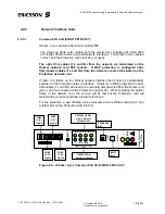
Common Part Unit (02HAT 00103 ACY)
IP 44G + Sync Common Part Unit for EDA 2530.
The Common Parts units contain both the electronics controlling the EDA 2530
(Controller, Matrix, Alarm Unit) and Network Interfaces. The Worker unit is located
in slot 1 and the Protection unit in slot 22 (not used).
The optic fibre cables (Tx and Rx) from the network are terminated on the
Worker network card SFP sockets. If MSP protection is configured optic
fibre/coaxial cables (Tx and Rx) from the network are also terminated on the
Protection network card.
If there is a failure on the Worker network interface then control is automatically
switched to the Protection network interface. If there is no MSP protection the optic
fibre cables (Tx and Rx) will need to be manually disconnected from the Worker unit
(slot 1) and re-connected to the Protection unit (slot 22). When replacing the optical
fibres to the network card, the service will be lost but the Protection card will
maintain the cross-connections and alarm functions.
For line protection, a pair of fibres can be terminated on the Worker card (slot 1) and
another pair on the Protection card (slot 22).
Figure 2.5 – IP 44G + Sync Common Part Unit 02HAT 00103 ACY
T
PWR
RS
232
ET
H
02HA
T
0010
3 A
C
Y
C
P
2
530
ETHERNET
RJ45
RS232
RJ12
RES
E
T
PORT
1/1/2/3
Gig Eth
1
2
3
4
L
I
N
K
A
C
T
I
V
I
T
Y
YELLOW LEDS =
Activity Status of
Ethernet Links
GREEN LEDS =
Ethernet Link Status
PORT
1/1/2/1
Gig Eth
PORT
1/1/2/4
Gig Eth
PORT
1/1/2/2
Gig Eth
T
PWR
RS
232
ET
H
02HA
T
0010
3 A
C
Y
C
P
2
530
ETHERNET
RJ45
RS232
RJ12
RES
E
T
PORT
1/1/2/3
Gig Eth
1
2
3
4
L
I
N
K
A
C
T
I
V
I
T
Y
1
2
3
4
L
I
N
K
A
C
T
I
V
I
T
Y
YELLOW LEDS =
Activity Status of
Ethernet Links
GREEN LEDS =
Ethernet Link Status
PORT
1/1/2/1
Gig Eth
PORT
1/1/2/4
Gig Eth
PORT
1/1/2/2
Gig Eth

