EDA 2530 Commissioning Procedure for Cable and Wireless Access
1/153 22-FGC 101 0239/2 Uen Rev J 2010-04-01
©
Ericsson AB 2010
Commercial in confidence
45 (200)
4.5
Power Supply Connection Unit Check
Switch ON Circuit Breaker MCB 1 at the top of the EDA 2530 cabinet. Check for –
50 volts on Pin 1 of the D-Type connector for Socket Vb1 on Power Supply
Connection Unit in slot 22. Switch OFF MCB 1 and check the –50 volts is removed.
Switch ON Circuit Breaker MCB 2 at the top of the EDA 2530 cabinet. Check for –
50 volts on Pin 5 of the D-Type connector for Socket Vb1. Switch OFF MCB 2 and
check the –50 volts is removed. Check for Earth (0 volts) on Pin 2 and Pin 4.
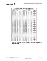
(Refer to Figure 4.1 for the layout of the 5 pin D-Type connector).
Reconnect the 5 pin D-Type connector to Socket Vb1 on the Power Supply
Connection Unit in slot 22. Secure the connector by tightening the two fixing
screws. Switch ON MCB 1 and MCB 2 and check the Green “VB1” power LED is lit
on the Power Supply Connection Unit in slot 22.
Switch ON Circuit Breaker MCB 3 at the top of the EDA 2530 cabinet. Check for –
50 volts on Pin 1 of the D-Type connector for Socket Vb2 on Power Supply
Connection Unit in slot 22. Switch OFF MCB 3 and check the –50 volts is removed.
Switch ON Circuit Breaker MCB 4 at the top of the EDA 2530 cabinet. Check for –
50 volts on Pin 5 of the D-Type connector for Socket Vb2. Switch OFF MCB 4 and
check the –50 volt is removed. Check for Earth (0 volts) on Pin 2 and Pin 4. (Refer
to Figure 4.1 for the layout of the 5 pin D-Type connector).
Reconnect the 5 pin D-Type connector to Socket Vb2 on the Power Supply
Connection Unit in slot 22. Secure the connector by tightening the two fixing
screws. Switch ON MCB 3 and MCB 4 and check the Green “VB2” power LED is lit
on the Power Supply Connection Unit in slot 22.
4.5.1
Labelling
Check that the Circuit Breakers MCB 1, MCB2, MCB 3 and MCB 4 or alternative
power supply Circuit Breakers are labelled according to the provisions of the
‘Installation Standard for EDA 2530 Equipment’.
Check that the optical links or cable, Customer side and Network side, are labelled
according to the provisions of the ‘Installation Standard for EDA 2530 Equipment’ or
that their terminations can be identified.
Check that the strips of the distribution frames, onto which the equipment is
terminated, are labelled according to the provisions of the ‘Installation Standard for
EDA 2530 Equipment’.
Check that the equipment racks and subracks are labelled according to the
provisions of the
‘Installation Standard for EDA 2530 Equipment’.
End of section

