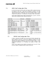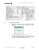
EDA 2530 Commissioning Procedure for Cable and Wireless Access
1/153 22-FGC 101 0239/2 Uen Rev J 2010-04-01
©
Ericsson AB 2010
Commercial in confidence
83 (200)
e.
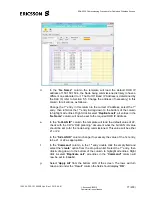
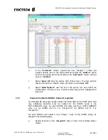
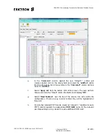
In the “
Command
” column, against the new “intLag//1/..” entries just
created, double click on the empty field and select the “
addPort
” option
from the drop-down list. All new entries in the “
Command”
column will now
be set to “
addPort
”.
f. Select
“
Apply All
” from the bottom LHS of the screen. The rows will turn
Green and under the “Result” column the field should display “
OK
”.
g. Select
“
Read Network
” near the top of the screen, this will confirm the
configuration, if there are any incorrect entries they will be highlighted at
this point.
7.7.2
Create S-VLANs for SHDSL Cards (If required)
The template file previously loaded creates the VLAN data for the ADSL slot 2 card
only, additional S-VLANs must be created for the SHDSL cards in the
“DATA_INBAND” name. For each SHDSL card there must be a “DATA_INBAND”
entry, e.g. for SHDSL slot 20 it is “intLag//1/20”, for SHDSL slot 21 it is
“intLag//1/21”.
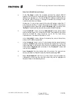
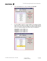
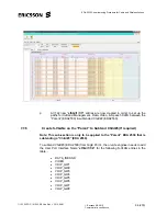
For each SHDSL card create a new “intLag//..” entry for the SHDSL slot(s), as
detailed in the following steps.
a.
Double left-click on the “
intLag//1/2
” entry in “User Port Interface Name”
column.


