RECEIVER ALIGNMENT
(Cont.)
RECEIVER ALIGNMENT
TEST EQUIPMENT REQUIRED (Or Equivalent)
1.
GE Test Set 4EX3A11, 4EX8K12, or 20,000 ohms-
per-volt millimeter with 1 volt scale
2.
AC Voltmeter
3.
FM Deviation Monitor
4.
Digital Voltmeter
5.
VOM
6.
RF Signal Generator (403-512 MHz)
7.
Frequency counter (Hewlett-Packard 5300B)
8.
Oscilloscope
9.
Audio Isolation Transformer (1:1) 19A116736P1 or
equivalent
10. 4 ohm 15 watt resistor
11. Tuning tool 19B800716P2
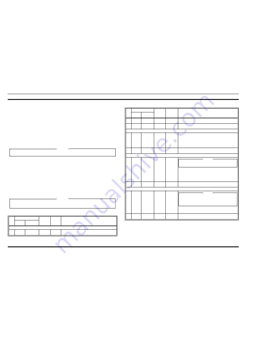
PRELIMINARY CHECKS AND ADJUSTMENTS
1.
Connect the black plug from the Test Set to the RF metering jack J101. Connect red system metering plug to J602, system
metering. Set Test Set to 1 volt scale. A 20,000 ohms-per-volt multimeter may be used when the GE Test Set is not
available.
2.
Preset C1-C7 to maximum height above top of tuning nut (10 mm above casting).
3.
Preset L509 to top of coil form and then turn clockwise 11 full turns.
4.
Preset L451 to top of coil form, then turn 15 turns clockwise.
5.
Preset L410, L411, L412, L507 and L508 to top of coil form and then turn clockwise 9 full turns.
6.
Apply power to radio and monitor the regulated 9 volt supply at J602-3. Adjust R703 if necessary to obtain 9
±
0.01 Vdc.
Use a digital multimeter.
ALIGNMENT PROCEDURE
NOTE
Refer to Figure 5 for location of tuning and adjustment controls.
NOTE
Before aligning the receiver or making any adjustments to the radio be sure that the output of the 9 volt regulator is set
for 9.0
±
0.1 Vdc.
STEP
METERING POSITION
TUNING
CONTROL
METER
READING
PROCEDURE
GE TEST
SET
MULTIMETER
(- TO A-)
LOCAL OSCILLATOR-BUFFER INJECTION
1.
G
(RX INJ)
J101-4
L452
Peak
Select desired channel or center tune frequency. Set Test Set to 1 volt
scale and tune L452 for maximum reading on Test Set.
ALIGNMENT PROCEDURE (Cont.)
STEP
METERING POSITION
TUNING
CONTROL
METER
READING
PROCEDURE
GE TEST
SET
MULTIMETER
(- TO A-)
3.
G
(RX INJ)
J101-4
C7
Dip
Tune C7 for a dip in Test Set reading.
4.
H
(RX MIX)
J101-3
C6, C7
L452
Peak
Tune C6 for maximum. Sequentially retune L452, C6 and C7 until there is
no further increase in meter reading.
FRONT END ALIGNMENT
5.
D
(IF AMP)
J602-10
C3
MAX
Connect RF signal generator to antenna jack J2. Set frequency to desired
receive channel or center tune frequency. Set modulation frequency to 1 kHz
and deviation to 3 kHz. Set input level to -10 dBm (70 mV).
Tune C3 for maximum indication on meter while reducing the input level
of the signal generator as required to keep the IF AMP reading from
saturating. (0.6 V typical).
6.
D
(IF AMP)
J602-10
C1, C5
C2, C4
Peak
Peak C1, C5, C2, C4 in sequence while reducing output level of signal
generator to prevent saturation.
RF SELECTIVITY
NOTE
If the IF amplifiers have been aligned using the alternate sweep alignment
method, proceed to Step 9.
7.
D
(IF AMP)
J602-10
L508, L507
L410, L411
and L412
Maximum
(See
Procedure)
Select a center frequency channel. Apply an on-frequency signal with 1 kHz
modulation to antenna jack J2. Set deviation to 3 kHz. Reduce signal level
to approximately 75% of saturated level shown on Test Set meter. While
making the following adjustments keep the signal level below saturation.
Tune L508, L507, L412, L411 and L410, in that order, for a peak reading.
Repeak coils until no further improvement in meter reading is noted.
8.
D
(IF AMP)
J602-10
C1-C5
Maximum
Repeak C1-C5.
FM DETECTOR/AUDIO PREAMPLIFIER
NOTE
The audio output is a balanced bridge circuit and requires all test equipment
connected across the speaker leads to the both AC and DC isolated from
ground.
Connect test equipment as shown in Figure 5.
9.
L509
0.35 - 0.5
VRMS
Set signal generator output for 1000
µ
V. Set R629 and volume control to
the center position. Monitor the speaker outputs (J602-6, 7) with an AC
voltmeter. Tune quadrature coil L509 for a peak reading.
10.
R629
Adjust R629, audio preamplifier level for nominal 300 mV RMS at VOL/SQ
HI (J603-14).
(Cont.)
LBI-31511
LBI-31511
12
Summary of Contents for LBI-31511B
Page 15: ... 19D901350 Sh 1 Rev 10 RECEIVER AUDIO AND SQUELCH WAVEFORM CHECKS LBI 31511 LBI 31511 14 ...
Page 16: ... 19D900977 Sh 1 Rev 20 MECHANICAL LAYOUT LBI 31511 LBI 31511 15 ...
Page 17: ... 19D900977 Sh 2 Rev 14 MECHANICAL LAYOUT LBI 31511 LBI 31511 16 ...
Page 18: ... 19D900980 Sh 1 Rev 4 INTERCONNECTION DIAGRAM LBI 31511 LBI 31511 17 ...


