26
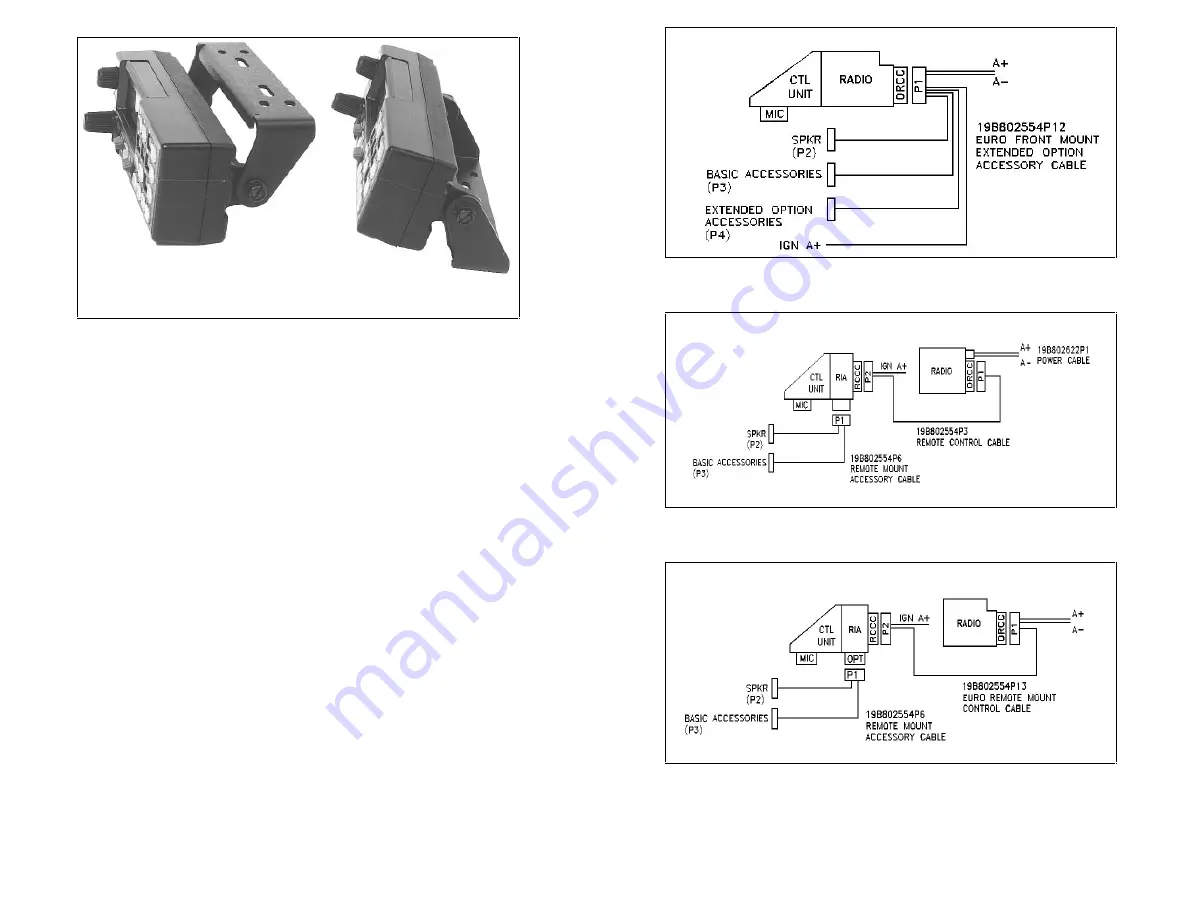
Figure 24 - Control Unit Mounting Bracket Installation
SPEAKER D2LS1F
The speaker kit includes the speaker, mounting bracket and connecting
cable. Mount the speaker so it is directed to the operator but does not
present a hazard in the event of an accident. The speaker may be
mounted on the lower edge of the instrument panel, the firewall or above
the windshield in some trucks.
1.
Use the mounting bracket as a template for locating the mounting
holes and mount the speaker as shown in Figure 25.
2.
Refer to the applicable installation procedures for connection of the
speaker to the accessory cable.
MICROPHONE HANGER AND/OR HOOKSWITCH
MOUNTING
The microphone hanger or hookswitch should be mounted in a location
convenient to the operator where it will not interfere with the safe
operation of the vehicle or be a hazard to the vehicle passengers. The
hanger or hookswitch is designed to be mounted with the open end of
the mounting button slot pointed upward. Use the hanger or hookswitch
as a template to mark and drill the mounting holes. Mount the hanger
or hookswitch with the self-tapping screws provided.
Top Mount
Bottom Mount
11
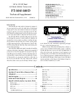
Figure 8 - Front Mount Extended Option Accessory
Interconnections (EURO Models Only)
Figure 9 - Remote Mount Basic Accessory Interconnections (USA
Models Only)
Figure 10 - Remote Mount Basic Accessory Interconnections (EURO
Models Only)
Summary of Contents for LBI-38901B
Page 1: ...Printed in U S A LBI 38901B Mobile Communications ORION MOBILE RADIO Installation Manual ...
Page 5: ...32 Figure 29 Cassette Assembly Schematic Diagram 5 Figure 3 Cables ...
Page 32: ...32 Figure 29 Cassette Assembly Schematic Diagram 5 Figure 3 Cables ...
Page 36: ...Printed in U S A LBI 38901B Mobile Communications ORION MOBILE RADIO Installation Manual ...


