18
Electrical installation guidelines include:
•
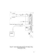
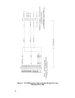
wiring the unit in accordance with the diagrams and
instructions provided in this manual
•
observing quality wiring techniques
Ericsson GE recommends that the unit be installed by one of the
many authorized General Electric Service Stations located throughout
the United States. Personnel at these centers are experienced in
installations of this type of equipment and can provide a safe, neat and
functional installation.
TOOLS REQUIRED
•
Electric Drill
•
No. 28 Drill Bit
•
Hole Saw
•
Phillips and Flat-Blade Screwdrivers
•
POZIDRIV Driver
SETTING THE DIP SWITCHES
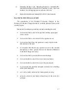
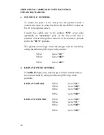
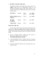
A DIP (Dual-Inline-Package) switch is located inside the unit that
allows it to be configured for several different operational modes.
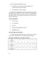
DIP SWITCH POSITION FACTORY SETTINGS
SW 3
(7-POSITION
SWITCH)
1
2
3
4
5
6
7
P1
VEH REPEATER
CHARGER
ON
OFF
ON
OFF
OFF
OFF
OFF
P2
ENHANCED VEH
CHARGER
ON
OFF
ON
ON
ON
OFF
OFF
11
2.
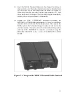
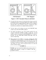
Insert the M-RK Personal Radio into the charger by sliding it
down into the slot. The radio should be inserted so that the front
of it faces the top of the charger unit (as shown in Figure 2).
When fully inserted, the radio extends approximately 1/8" inch
above the front of the charger. The fast charge begins immediately
and the yellow charge indicator is illuminated.
4.
Engage the UDC INTERFACE connector by
turning the
ROTARY LATCH KNOB approximately 1/4 turn in a clockwise
direction until it clicks into the latched position. This onnects the
M-RK radio to the Vehicular Charger's audio circuits and to the
external antenna. The radio cannot be removed from this position
until the UDC INTERFACE connector is unlatched using the
RELEASE BUTTON in the center of the ROTARY LATCH
KNOB.
Figure 2 - Charger with M-RK II Personal Radio Inserted

