background image

Installing the RMM

RMM

4.

Turn the O&M plate counter clockwise to cover the RMM slot and the O&M
port, and fasten the screws. Recommended torque is 1.1 Nm.

15

13/1531-HRA 901 17/9 Uen B

|

2016-03-04

Summary of Contents for MINI-LINK 6351

Page 1: ...Installing a MINI LINK 6351 INSTALLATION INSTRUCTIONS 13 1531 HRA 901 17 9 Uen B...

Page 2: ...permission of the copyright owner Disclaimer The contents of this document are subject to revision without notice due to continued progress in methodology design and manufacturing Ericsson shall have...

Page 3: ...11 4 Installing the RMM 13 5 Installing the MINI LINK 6351 17 5 1 Assembling the MINI LINK 6351 17 5 2 Installing the MINI LINK 6351 on a Wall 19 5 3 Installing the MINI LINK 6351 in a Mast 22 5 4 Ins...

Page 4: ...Installing a MINI LINK 6351 13 1531 HRA 901 17 9 Uen B 2016 03 04...

Page 5: ...hernet PoE Note If you configure the packet radio using a script on the RMM and that script turns on the transmitter do not connect the packet radio to power until after mounting the packet radio and...

Page 6: ...Installing a MINI LINK 6351 1 2 3 Figure 2 Connectors on MINI LINK 6351 Table 1 Connectors Item Connector 1 EARTH 2 PoE 3 O M and ALIGNMENT 2 13 1531 HRA 901 17 9 Uen B 2016 03 04...

Page 7: ...the following documents has been understood by the persons performing the procedures Personal Health and Safety Information Reference 1 System Safety Information Reference 3 Supplementary Safety Info...

Page 8: ...Installing a MINI LINK 6351 4 13 1531 HRA 901 17 9 Uen B 2016 03 04...

Page 9: ...Operation 0 Temperature 033 C to 55 C 027 F to 131 F Measure outdoor temperature in an open unshielded area preferably close to the radio The sensor must be protected from the sun Minimum distance to...

Page 10: ...1 For outdoor screws and nuts 1 Manufacturer Molykote Dow Corning GmbH Pelkovenstrasse 152 D 8000 Munich 50 Germany LSB 903 36 8650 Figure 3 Extended T handle Hex Key 3 3 2 Outdoor Cabling Table 3 Too...

Page 11: ...Pozidrive Accessories Cable Boot Black 1 RPV310907 1 Connector RJ45 Plug RPV310907 01 2 Teleg rtner Crimp Tool N00001A0002 3 4 Slotted screwdriver Dimension 2 5 0 5 mm 1 Only required if connecting t...

Page 12: ...s positioned on the cardboard box and on the unit For example the label contains the following information Product number ordering code Index number Revision state Manufacturing date Check the product...

Page 13: ...ng for Installation 3 4 2 MINI LINK 6351 RMM Figure 6 Items Included with the MINI LINK 6351 3 4 3 RMM The RMM comes included with the delivery in a small plastic bag 9 13 1531 HRA 901 17 9 Uen B 2016...

Page 14: ...51 3 4 4 Alignment Camera Figure 7 MINI LINK 6351 Alignment Camera The alignment camera is ordered separately 3 4 5 Outdoor Cabling Table 5 shows the items required for the PoE cabling 10 13 1531 HRA...

Page 15: ...n ended AC cable Supplement with a connector suitable for your location 2 The delivery includes an AC cable with a North American connector 3 5 Installing the MINI LINK Alignment App To install the MI...

Page 16: ...Installing a MINI LINK 6351 12 13 1531 HRA 901 17 9 Uen B 2016 03 04...

Page 17: ...be performed in dry conditions The O M plate must always be closed after accessing the MINI LINK 6351 Caution Electrostatic Discharge ESD may damage the equipment Always use an approved ESD wrist str...

Page 18: ...expose the RMM slot and O M port 3 Hold the RMM with the notched corner on the left side while directed away from you and insert the RMM in the RMM slot Note Regardless of the direction of the printe...

Page 19: ...Installing the RMM RMM 4 Turn the O M plate counter clockwise to cover the RMM slot and the O M port and fasten the screws Recommended torque is 1 1 Nm 15 13 1531 HRA 901 17 9 Uen B 2016 03 04...

Page 20: ...Installing a MINI LINK 6351 2 16 13 1531 HRA 901 17 9 Uen B 2016 03 04...

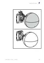
Page 21: ...51 To assemble the MINI LINK 6351 1 If you want horizontal polarization align the marking A on the antenna with the marking H on the antenna arm If you want vertical polarization align the marking A o...

Page 22: ...a MINI LINK 6351 A V H A A Horizontal polarization Vertical polarization Figure 8 Choosing Polarization 2 Mount the packet radio on the antenna arm using the two screws 18 13 1531 HRA 901 17 9 Uen B...

Page 23: ...unt the wall bracket on the wall Use screws and fixings appropriate for the type of wall on the site Make sure to mount the wall bracket oriented as shown below Note Use a spirit level to make sure th...

Page 24: ...Installing a MINI LINK 6351 2 Fit the MINI LINK 6351 to the wall attachment and tighten the two screws 20 13 1531 HRA 901 17 9 Uen B 2016 03 04...

Page 25: ...Installing the MINI LINK 6351 1 2 21 13 1531 HRA 901 17 9 Uen B 2016 03 04...

Page 26: ...rement The other end of the earthing cable must be connected to mast ground 1 Connect the earthing cable to the packet radio Connect the other end of the earthing cable to mast ground 5 3 Installing t...

Page 27: ...Installing the MINI LINK 6351 1 Mount the wall bracket on the mast Note Use a spirit level to make sure that the wall bracket is mounted level 23 13 1531 HRA 901 17 9 Uen B 2016 03 04...

Page 28: ...Installing a MINI LINK 6351 2 Fit the MINI LINK 6351 to the wall bracket and tighten the two screws 24 13 1531 HRA 901 17 9 Uen B 2016 03 04...

Page 29: ...Installing the MINI LINK 6351 1 2 25 13 1531 HRA 901 17 9 Uen B 2016 03 04...

Page 30: ...nnect the other end of the earthing cable to mast ground 5 4 Installing PoE Equipment and Cable PoE provides the MINI LINK 6351 with both traffic and power through a single cable It is also possible t...

Page 31: ...tdoor Indoor PoE injector Power Ethernet Packet radio A B Packet radio Surge protector PoE injector Power Ethernet Figure 10 PoE Installation with PoE injector Mounted Indoor A and Outdoor B 27 13 153...

Page 32: ...n an environment where there is no risk of lightning strike near the equipment or cable The PoE cable is shorter than 20 meters The RJ45 connector shall always be connected to a shielded jack 5 4 1 2...

Page 33: ...50 meters 55 yards It is also recommended to ground the cable before sharp bends Make sure the grounding is properly done to improve protection against overvoltage 5 4 2 Testing the PoE Cable Make sur...

Page 34: ...the MINI LINK 6351 Mount and ground the Ethernet surge protector by following the installation instruction enclosed in the surge protector delivery 5 4 5 Connecting the PoE Cable to the MINI LINK 6351...

Page 35: ...ble to the Ethernet surge protector c Connect the Ethernet cable to the PoE injector If not using an Ethernet surge protector connect the PoE cable Ethernet connector to the PoE injector 5 4 6 Clampin...

Page 36: ...le and multiple MINI LINK 6351 installations A maximum number of three clamps can be stacked upon each other for fitting either horizontally or vertically Secure the clamps to each other by nut and bo...

Page 37: ...ace it in cable clamps at 1 m intervals 1 m 1 m 1 m 1 m 1 m 1 m 1 m 2 If a single clamp is used per cable section If the clamp is fitted vertically fasten the clamp with two straps and tighten the str...

Page 38: ...included in the stacking kit through the first clamp fit the clamp to the mast and tighten the straps by hand Stack the other clamps and secure the clamps with a nut b If metal straps are used positio...

Page 39: ...turn to cut the excess tail off LSD 349 20 5 4 7 Grounding the PoE Cable This section describes how to ground the PoE cable Danger The lower part of the PoE cable must be grounded for example before...

Page 40: ...rature of the butyl sealing compound must not be below 20 C 4 F during installation Grounding Procedure Caution Make sure to strip the PoE cable at the specified dimension and center the earthing kit...

Page 41: ...earthing kit body A around the stripped part of the cable A E 3 Make sure the butyl sealing compound inside the earthing kit body is positioned on the outer jacket 4 Connect the earthing cable C to th...

Page 42: ...751 6 Connect the other end of the earthing cable to mast ground 5 4 8 Fitting the Wall Gland The wall gland installation is to be performed from the outside of the building and is only applicable for...

Page 43: ...you reach a gap of 0 1mm between the layers held against the cable A B 8739 4 Lubricate both the inside and the outside of the wall gland using the lubricant enclosed in the delivery Note Ensure that...

Page 44: ...t of the wall gland on top of the cable and insert it into the wall 8729 7 Tighten the four screws crosswise Recommended maximum torque is 4 Nm appropriate torque depends on several things for example...

Page 45: ...MINI LINK 6351 is not configured using a script on the RMM perform an initial setup See Installation and Commissioning Overview If the MINI LINK 6351 is configured using a script on the RMM continue w...

Page 46: ...Installing a MINI LINK 6351 42 13 1531 HRA 901 17 9 Uen B 2016 03 04...
Page 47: ...areas involve the risk of accidents caused by falling or by falling objects 7 1 Preparing for Antenna Alignment To prepare for aligning the antenna 1 Make sure that the personnel at both sites can co...

Page 48: ...s b Press the select button E to enter the WIRELESS menu in the LCD status screen D c If the LCD status screen D does not show GOPRO APP press the power button A repeatedly to until the screen shows G...

Page 49: ...Aligning the Antenna C E D A B 45 13 1531 HRA 901 17 9 Uen B 2016 03 04...

Page 50: ...the camera Wi Fi using the camera Wi Fi SSID and password The default values are SSID GOPRO BP ALPHANUMERIC SEQUENCE See the SSID label on the camera for details Password goprohero For details on how...

Page 51: ...nto the slot on the underside of the packet radio Make sure that the camera bracket clicks into place B Insert the camera bracket 1 into the camera adapter 2 and push the camera adapter onto the anten...

Page 52: ...ing a MINI LINK 6351 B 1 2 6 On the mobile device start the MINI LINK Alignment app 7 Select the camera Wi Fi 8 Enter the password for the camera Wi Fi 9 Tap Connect 48 13 1531 HRA 901 17 9 Uen B 2016...

Page 53: ...Antenna 10 Tap Start alignment The Alignment screen opens 11 Loosen the screws A and adjust the antenna until the far end antenna is visible in the MINI LINK Alignment app 49 13 1531 HRA 901 17 9 Uen...

Page 54: ...aking an adjustment before the MINI LINK Alignment app shows the change It is therefore recommended to adjust the antenna in small steps with a two second pause in between to allow the change to becom...

Page 55: ...gning the Antenna 12 Continue adjusting the antenna in small steps until the far end antenna is located in the center of the circle in the middle of the screen A 51 13 1531 HRA 901 17 9 Uen B 2016 03...

Page 56: ...alignment in the following ways Using Commissioning Guide Using a voltmeter described in this section The voltmeter is used to measure and find the maximum alignment value during the alignment proced...

Page 57: ...mum value 2 Tighten the locking screws and nuts Follow the antenna installation instruction when the maximum value is found 7 3 2 Adjusting Elevation 1 Adjust the antenna vertically for maximum alignm...

Page 58: ...0 60 70 80 90 100 0 0 5 1 0 1 5 2 0 2 5 Alignment Level V 25 mV dB Formula RF 40 Alignment level in volts 120 20 8823 Figure 18 RF Input Level as a Function of the Alignment Level Table 6 Accuracy wit...

Page 59: ...a 2 Compare the RF input level with the one specified in the installation data form calculated for the system during path calculation and check that the desired level is obtained 55 13 1531 HRA 901 17...

Page 60: ...Installing a MINI LINK 6351 56 13 1531 HRA 901 17 9 Uen B 2016 03 04...

Page 61: ...eference List 1 Personal Health and Safety Information 124 46 2885 2 Supplementary Safety Information for MINI LINK 124 46 HSD 101 16 1 3 System Safety Information 124 46 2886 57 13 1531 HRA 901 17 9...

Reviews: