Preventive Maintenance and Fault-finding
5.5.3
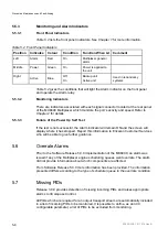
Monitoring and Alarm Indicators
5.5.3.1
Front Panel Indicators
lists the front panel indicators. See
Chapter 1
for more information.
Table 5.2 Front Panel Indicators
Position Indicates Colour
Condition
Function When Lit Comment
Left Alarm
Red On
Multiplexer general
alarm
Middle Power Green On
Power is applied to
the unit
Right
Active Blue
Off
On
Backup unit
Active unit
Used in redundancy
systems
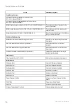
gives the conditions that will light the Alarm indicator on the front panel
and operate the Alarm relay.
5.5.3.2
Monitoring Indicators
There are indicators associated with each signal connector located at the rear panel
of the MX8400 Multiplexer which monitors the port’s activity and speed. Refer to
Chapter 2
for details.
5.5.3.3
Failure of the Power Up Self Test
If the test is not successful, the Alarm indicator will remain ON and the screen will
display where it has stopped. Report this information to Ericsson Customer Services
who will be able to give further guidance.
5.6
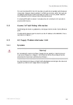
Overrate Alarms
Prior to the Software Release 5.0.0 implementation of the MX8400, an alarm was
issued if any of the Multiplexer engine scheduling queues went overrate. The alarm
did not provide information about which components are affected.
From Software Release 5.0.0 more information has been provided. The information
presented differs according to the type of scheduler queue in the overrate condition.
5.7
Missing PIDs
Release 3.0.0 provides detection of missing incoming PIDs and raises appropriate
alarms to nCompass Control.
All PIDs which are required for an output transport stream are automatically included
in a list of incoming PIDs to be monitored. It is possible to define, as an nCC
configurable parameter, a list of PIDs to be excluded from monitoring.
2/1553-FGC 101 1014 Uen B
5-8
Summary of Contents for MX8400
Page 1: ...MX8400 Multiplexer Software Version 5 2 0 and later REFERENCE GUIDE 2 1553 FGC 101 1014 Uen B...
Page 26: ...Installing and Powering Up 2 1553 FGC 101 1014 Uen B 2 4 BLANK...
Page 94: ...Operating the Multiplexer using nCompass Control 2 1553 FGC 101 1014 Uen B 4 18 BLANK...
Page 96: ...Preventive Maintenance and Fault finding 2 1553 FGC 101 1014 Uen B 5 2 BLANK...
Page 146: ...Technical Specification 2 1553 FGC 101 1014 Uen B B 20 BLANK...
Page 148: ...Static Parameters 2 1553 FGC 101 1014 Uen B C 2 BLANK...
Page 186: ...Redundancy Modes 2 1553 FGC 101 1014 Uen B E 2 BLANK...
Page 192: ...IP Protocols 2 1553 FGC 101 1014 Uen B F 2 BLANK...
Page 196: ...IP Protocols 2 1553 FGC 101 1014 Uen B F 6 Figure F 3 Editing Stack Download Ports...
Page 198: ...ProMPEG FEC Support for IP Streaming 2 1553 FGC 101 1014 Uen B G 2 BLANK...
Page 204: ...Setting up the SFN Functionality 2 1553 FGC 101 1014 Uen B H 2 BLANK...
Page 212: ...Setting up the SFN Functionality 2 1553 FGC 101 1014 Uen B H 10 BLANK...
Page 214: ...PSIG Support 2 1553 FGC 101 1014 Uen B I 2 BLANK...
Page 220: ...BISS Support 2 1553 FGC 101 1014 Uen B J 2 BLANK...

