Preventive Maintenance and Fault-finding
5.9.2
Power Indicator Unlit
When the Multiplexer Power indicator is unlit, fault-find the problem as detailed in
.
Table 5.3 Power Indicator Unlit Fault-finding
Step
Action
If Result of Action is
Yes…
If Result of Action is No…
1
Check Power indicator
. Is
the Multiplexer still working?
If the Multiplexer is clearly
working normally then the
Power
indicator
itself is
probably at fault. Call a
Service Engineer.
Proceed to next step.
2
Check Power Source
.
Connect a known-working
piece of equipment to the
power source outlet. Does it
work?
The problem lies within the
Multiplexer or power cable.
Proceed to next step.
The problem lies with the
power source. Check building
circuit breakers, fuse boxes,
etc. If problem persists, contact
the electricity supplier.
3
Check Power Cable and
Fuse
. Unplug the power
connector from the Multiplexer
and try it in another piece of
equipment. Does it work?
The problem lies within the
Multiplexer. Proceed to next
step.
The problem lies with either
the cable itself, or with the fuse
in the plug. Replace the fuse or
try to substitute another cable.
4
Check PSU Module and
Fuse
. Ensure the power
connector is unplugged.
Remove the fuse from the rear
panel connector and inspect it.
Has the fuse blown?
Replace the fuse with one of
the correct type and rating
(see
Annex B Technical
Specification
). If the PSU still
does not work, unplug the
power cable and call a
Service Engineer.
Possible problem with the PSU
module. Call a Service
Engineer.
5.9.3
PSU Redundant Operation and Hot Swap
The power supplies have integrated Or-ing FETs/diodes and are designed to
support hot swap in redundant power systems. The PSUs current-share when both
are active, but a single PSU is capable of fully powering the MX8400 Multiplexer.
Exercise care when hot swapping any power supply.
Caution!
The PSU used in the MX8400 is designed to allow for hot swapping in the event of a
failure. Ideally, if the MX8400 is fitted with dual PSUs, the failed PSU should be
replaced during a service window to prevent accidental removal of the working PSU.
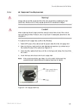
Note:
The upper PSU at the front panel corresponds to the upper AC supply
receptacle at the rear panel. The lower PSU at the front panel corresponds
to the lower AC supply receptacle at the rear panel.
2/1553-FGC 101 1014 Uen B
5-10
Summary of Contents for MX8400
Page 1: ...MX8400 Multiplexer Software Version 5 2 0 and later REFERENCE GUIDE 2 1553 FGC 101 1014 Uen B...
Page 26: ...Installing and Powering Up 2 1553 FGC 101 1014 Uen B 2 4 BLANK...
Page 94: ...Operating the Multiplexer using nCompass Control 2 1553 FGC 101 1014 Uen B 4 18 BLANK...
Page 96: ...Preventive Maintenance and Fault finding 2 1553 FGC 101 1014 Uen B 5 2 BLANK...
Page 146: ...Technical Specification 2 1553 FGC 101 1014 Uen B B 20 BLANK...
Page 148: ...Static Parameters 2 1553 FGC 101 1014 Uen B C 2 BLANK...
Page 186: ...Redundancy Modes 2 1553 FGC 101 1014 Uen B E 2 BLANK...
Page 192: ...IP Protocols 2 1553 FGC 101 1014 Uen B F 2 BLANK...
Page 196: ...IP Protocols 2 1553 FGC 101 1014 Uen B F 6 Figure F 3 Editing Stack Download Ports...
Page 198: ...ProMPEG FEC Support for IP Streaming 2 1553 FGC 101 1014 Uen B G 2 BLANK...
Page 204: ...Setting up the SFN Functionality 2 1553 FGC 101 1014 Uen B H 2 BLANK...
Page 212: ...Setting up the SFN Functionality 2 1553 FGC 101 1014 Uen B H 10 BLANK...
Page 214: ...PSIG Support 2 1553 FGC 101 1014 Uen B I 2 BLANK...
Page 220: ...BISS Support 2 1553 FGC 101 1014 Uen B J 2 BLANK...

