Introduction
A system dependant delay constant is defined at the system configuration stage.
The MX8400 calculates the latency for individual Encoders and sets buffers
appropriately to ensure all Encoders within the system experience the same network
delay. This is achieved by ensuring the delay an Encoder service experiences is
equal to the predefined system delay constant.
An Encoder at a remote site will experience a larger delay in the network and is
therefore delayed less within the MX8400 input than an local based Encoder service
which is part of that the same Remote Reflex group.
1.3.3.4
Reflex Static Parameters
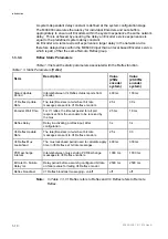
lists all the static parameters associated with the Reflex function.
Table 1.3 Static Parameters [Reflex]
Name
Description Value
(25Hz
encoder
system)
Value
(29.97Hz
encoder
system)
Status Update
Period
Interval between V4 Reflex status reports from
encoder.
400 ms
133 ms
V1 Reflex Update
Rate
The rate(times/sec) at which set bit rate
messages are sent to V1 Reflex encoders.
25 s
30 s
Encoder Wait Time
For V1 reflex, the timeout period for all poll
responses from the encoders to be received by
the mux.
25 ms
18 ms
Reflex Delay
Delay in activating a reflex input, after
configuration.
3 s
3 s
V4 Reflex Update
Rate
The rate(times/sec) at which set bit rate
messages are sent to V4 Reflex encoders.
25 s
30
V4 Reflex Mux
Lookahead
The mux lookahead period used to calculate apply
time in V4 Reflex set bit rate messages.
400 ms
330 ms
PCR exchange
interval
Interval between mux sending PCR Exchange
messages to V4 Reflex encoders.
1000 ms
1000 ms
Bit rate On Failure
Delay ms
Delay period before assuming configured bit rate
on failure value for failing V4 Reflex encoder
2500 ms
2500 ms
Reflex broadcast
V1 Reflex broadcast messaging - on/off
off
off
Note:
In
Table 1.3
, V1 Reflex refers to Reflex and V4 Reflex refers to Remote
Reflex.
2/1553-FGC 101 1014 Uen B
1-10
Summary of Contents for MX8400
Page 1: ...MX8400 Multiplexer Software Version 5 2 0 and later REFERENCE GUIDE 2 1553 FGC 101 1014 Uen B...
Page 26: ...Installing and Powering Up 2 1553 FGC 101 1014 Uen B 2 4 BLANK...
Page 94: ...Operating the Multiplexer using nCompass Control 2 1553 FGC 101 1014 Uen B 4 18 BLANK...
Page 96: ...Preventive Maintenance and Fault finding 2 1553 FGC 101 1014 Uen B 5 2 BLANK...
Page 146: ...Technical Specification 2 1553 FGC 101 1014 Uen B B 20 BLANK...
Page 148: ...Static Parameters 2 1553 FGC 101 1014 Uen B C 2 BLANK...
Page 186: ...Redundancy Modes 2 1553 FGC 101 1014 Uen B E 2 BLANK...
Page 192: ...IP Protocols 2 1553 FGC 101 1014 Uen B F 2 BLANK...
Page 196: ...IP Protocols 2 1553 FGC 101 1014 Uen B F 6 Figure F 3 Editing Stack Download Ports...
Page 198: ...ProMPEG FEC Support for IP Streaming 2 1553 FGC 101 1014 Uen B G 2 BLANK...
Page 204: ...Setting up the SFN Functionality 2 1553 FGC 101 1014 Uen B H 2 BLANK...
Page 212: ...Setting up the SFN Functionality 2 1553 FGC 101 1014 Uen B H 10 BLANK...
Page 214: ...PSIG Support 2 1553 FGC 101 1014 Uen B I 2 BLANK...
Page 220: ...BISS Support 2 1553 FGC 101 1014 Uen B J 2 BLANK...

