Operating the Multiplexer using nCompass Control
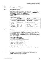
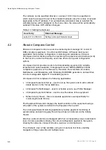
The netmask can be specified directly or a value of 0.0.0.0 can be specified, in
which case the value will be set to the standard netmask value for a class of network
appropriate to the IP address. If an automatically calculated value is selected the
calculated value will be displayed on the menu. Also, the value will be automatically
updated if the class of IP address changes.
Table 4.3 Setting the Netmask
User Entry
Returned Message
setip ctrl 1 m 255 0.0.0
Setting control port Network mask
4.2
About nCompass Control
Ericsson nCompass Control is a service-oriented system manager for control of
DVB-compliant equipment. It is a Microsoft Windows XP based client server
application that provides configuration, monitoring and redundancy. Ericsson
nCompass Control clients provide the operator with a graphical user interface (GUI)
to the server's on-line functionality, as well as off-line set up and configuration
options.
nCompass Control provides control of all broadcasting equipment for satellite,
terrestrial and cable headends. It integrates Ericson’s MPEG-2/MPEG-4/DVB-
compliant equipment such as Receivers, Decoders, Descramblers, Encoders,
Multiplexers, and Modulators, with third-party ECM/EMM generators, and switches
into one manageable digital TV broadcasting system.
nCompass Control comprises the following applications:
•
nCompass Equipment Set up - used to set up the system and to add, edit and
delete devices in the Set up database.
•
nCompass Profile Manager - used to schedule events, see Profile Manager.
•
nCompass Equipment Status - used to view the status of the equipment.
•
Reflex Activity Viewer - this is a separate application used specifically for
monitoring Encode bit rate.
The Equipment Status GUI displays the health condition of the equipment using a
schematic of the system as defined in the Equipment Set up GUI.
The nCompass Status Monitoring application provides graphical monitoring of
system status and alarm logging. Real-time activity is monitored via the Activity
Viewer.
All active (current) alarms are displayed with their corresponding colour-coded alarm
level. It is also possible to display the current configuration applied to the system,
showing the networks, transport streams, services, and components.
The schematic view is fully scalable, using zoom and pan functions, enabling
navigation of large networks and multiple views.
2/1553-FGC 101 1014 Uen B
4-4
Summary of Contents for MX8400
Page 1: ...MX8400 Multiplexer Software Version 5 2 0 and later REFERENCE GUIDE 2 1553 FGC 101 1014 Uen B...
Page 26: ...Installing and Powering Up 2 1553 FGC 101 1014 Uen B 2 4 BLANK...
Page 94: ...Operating the Multiplexer using nCompass Control 2 1553 FGC 101 1014 Uen B 4 18 BLANK...
Page 96: ...Preventive Maintenance and Fault finding 2 1553 FGC 101 1014 Uen B 5 2 BLANK...
Page 146: ...Technical Specification 2 1553 FGC 101 1014 Uen B B 20 BLANK...
Page 148: ...Static Parameters 2 1553 FGC 101 1014 Uen B C 2 BLANK...
Page 186: ...Redundancy Modes 2 1553 FGC 101 1014 Uen B E 2 BLANK...
Page 192: ...IP Protocols 2 1553 FGC 101 1014 Uen B F 2 BLANK...
Page 196: ...IP Protocols 2 1553 FGC 101 1014 Uen B F 6 Figure F 3 Editing Stack Download Ports...
Page 198: ...ProMPEG FEC Support for IP Streaming 2 1553 FGC 101 1014 Uen B G 2 BLANK...
Page 204: ...Setting up the SFN Functionality 2 1553 FGC 101 1014 Uen B H 2 BLANK...
Page 212: ...Setting up the SFN Functionality 2 1553 FGC 101 1014 Uen B H 10 BLANK...
Page 214: ...PSIG Support 2 1553 FGC 101 1014 Uen B I 2 BLANK...
Page 220: ...BISS Support 2 1553 FGC 101 1014 Uen B J 2 BLANK...

