For motorcycle models equipped with gas tank fairing
The cable may be routed from the saddle area, under the fairing, around
the left side of the gas tank filler pipe, and up to the area of the control unit.
The fairing may have to be notched to provide entrance and exit space. Run
the control cable as directed in Steps 1 thru 3.
1. Remove all the screws securing the fairing. Next, unscrew and remove the
gas tank cap and lift off the fairing. Replace the gas cap immediately.
2.
Run the cables from the saddle area up the left side of the gas tank to the
area of the control unit.
Always replace the gas cap as soon as the fairing is replaced/removed.
This is necessary to reduce the possibility of an explosion as well as to
prevent drill shavings or other debris from getting into the gas tank.
WARNING
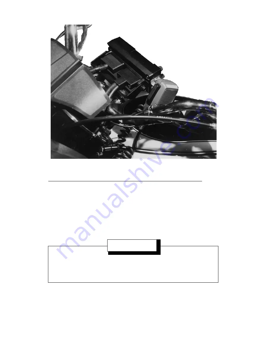
Figure 14 - Control Unit Connections
26
CONTROL UNIT MOUNTING
Mount the control unit within convenient reach of the operator, and where
it will not interfere with the safe operation of the motorcycle. Figure 9 shows
a typical installation of the control unit and microphone. Note also, the location
of the option switch for the Headset Option.
Due to the large number of different makes and models of motorcycles, it
is up to the installer to decide how to mount the control unit and optional
equipment. Mounting brackets for all makes and models are not available from
the factory, making it necessary to obtain a custom made bracket.
When designing and mounting the control unit bracket, the following
guidelines should be considered.
•
The installation must NOT interfere with steering or operation of the
motorcycle.
•
Mounting locations must NOT interfere with the driver or with instru-
ment visibility.
•
The installation should provide easy access to the radio operating
controls.
•
Rounded corners/edges should be employed to the maximum extent
possible.
Figure 9 - Typical Control Unit Installation
19
Summary of Contents for ORION
Page 4: ...Figure 1 Typical Orion Motorcycle Installation 4 ...
Page 8: ...Figure 2 Typical Motorcycle Kit 8 ...
Page 15: ...Figure 5 Radio Installation Harley Davidson Motorcycles 188D6803 Sh 1 Rev 2A 15 ...
Page 16: ...Figure 6 Radio Installation Kawasaki K1000 188D6803 Sh 2 Rev 2A 16 ...
Page 18: ...Figure 7 Case Mounting Bracket And Case Assembly Figure 8 Radio Connections 18 ...
Page 21: ...Figure 10 Control Unit Mounting Assembly 188D6804 Rev 2 21 ...
Page 25: ...Figure 12 Option Cable Stored Beneath Saddle Area Figure 13 Triangular Frame Assembly 25 ...
Page 32: ...Interconnection Diagram USA version 188D6783 Sh 1 Rev 2 32 ...
Page 33: ...Interconnection Diagram USA version 188D6783 Sh 1 Rev 2 33 ...
Page 34: ...Interconnection Diagram European Version 188D6783 Sh 2 Rev 2 34 ...
Page 35: ...Interconnection Diagram European Version 188D6783 Sh 2 Rev 2 35 ...
Page 36: ...Control Cable USA Version Remote Mount Motorcycle Extended 19B802554P23 Rev 20 36 ...
Page 37: ...Motorcycle Accessory Cable 19B802554P24 Rev 20 37 ...
Page 38: ...Control Power Cable European Version Remote Mount Motorcycle Extended 19B802554P25 Rev 20 38 ...
Page 39: ...Power Control Cable USA Version 19B802622P2 Sh 2 Rev 2A 39 ...
Page 40: ...Motorcycle Radio Case Assembly 188D6465 Sh 1 Rev 3 40 ...


