Unit Description, ASU
P008375B
CDU
CXU
Antenna
connection
fields
ASU
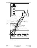
Figure 98
ASU location in the RBS 2206
12.1.2
Couplers
The ASU consists of 6 couplers, performing the following functions:
•
200
resistor to ground for cable supervision purposes
•
Directional coupler
•
Attenuator
•
Switch to select between high and low attenuation
•
Built-in overvoltage protection
A schematic view of one coupler is shown Figure 99 on page 173.
172 (485)
EN/LZT 720 0008
P2A
2001-11-28
© Ericsson Radio Systems AB
— All Rights Reserved —
P
re
li
m
in
a
ry
Summary of Contents for RBS 2106
Page 2: ...P r e l i m i n a r y ...


