Card Descriptions
6.1.1
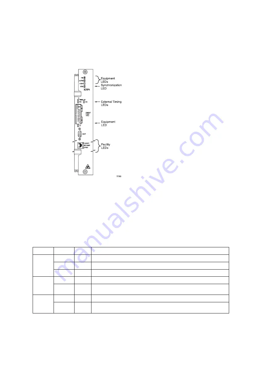
Controller Card LEDs
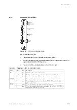
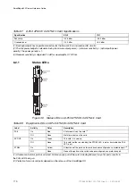
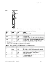
Figure 34
LEDs on Controller Cards
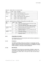
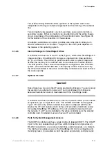
Each controller card has:
•
Four equipment LEDs—Indicate current card status
•
One synchronization and two external timing LEDs—Indicate the status of
any connected external timing source
•
Two facility LEDs—Indicate status of the Ethernet port
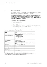
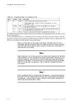
Table 84
Equipment LEDs on Controller Cards
Label
Activity
Color
Description
On
Red
A failure exists on the controller card.
(1)
Blinking
Red
Standby controller is being synchronized with the active controller.
(2)
FAIL
Off
None
No failure exists on the controller card.
On
Green
This controller card is the active controller.
ACTIVE
Off
None
This controller card is either on standby (the STDBY LED is on) or has failed
(the FAIL LED is on).
On
Yellow
This controller card is the standby controller for the system.
STDBY
Off
None
This controller card is either the active controller for the system (the ACTIVE LED
is on) or has failed (the FAIL LED is on).
109
27/153 30-CRA 119 1170/1 Uen A
|
2010-04-09
Summary of Contents for SmartEdge 600
Page 1: ...SmartEdge 600 Router Hardware Guide Release 6 3 INSTALLATION 27 153 30 CRA 119 1170 1 Uen A ...
Page 6: ...SmartEdge 600 Router Hardware Guide 27 153 30 CRA 119 1170 1 Uen A 2010 04 09 ...
Page 26: ...SmartEdge 600 Router Hardware Guide 20 27 153 30 CRA 119 1170 1 Uen A 2010 04 09 ...
Page 108: ...SmartEdge 600 Router Hardware Guide 102 27 153 30 CRA 119 1170 1 Uen A 2010 04 09 ...
Page 112: ...SmartEdge 600 Router Hardware Guide 106 27 153 30 CRA 119 1170 1 Uen A 2010 04 09 ...

