Hardware Control and Troubleshooting
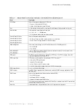
Table 51
Definitions of Terms
Term
Definition
AU-n
Administrative unit, level
n
BER
Bit error rate
BIP
Bit Interleaved Parity
BTC
Bridging Transmission Convergence
circuit pack
Any traffic or controller card
DCC
Data communications channel
FEAC
Far end alarm condition
PLCP
Physical Layer Convergence Protocol
TU-n
Tributary unit, level n
VC-n
Virtual container, level n
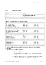
Caution!
Risk of equipment damage. Ensure that the fuses in the external fuse panel
are suitably rated for the installation in accordance with the National Electrical
Code (in the United States) or applicable local jurisdiction (outside the United
States) installation requirements.
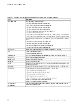
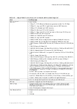
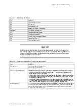
Table 52
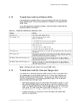
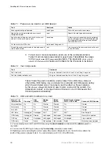
Problems Indicated by Power and Alarm LEDs
Term
Definition
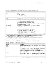
FAN (red) is on.
One or more fans are not operating.
Replace the fan and alarm unit.
PWR A or PWR B (green) is off.
No power is present at the A-side or B-side power input; perform the following checks or actions:
• Remove and check the fuse for the A-side or B-side DC power source at the external fuse
panel. Replace the fuse, if necessary.
• Remove the fuse for the A-side or B-side power source at the external fuse panel; then check the
connections for the A-side or B-side power source at the external fuse panel. Correct any loose
connections, and replace the fuse.
• Remove the fuses for both power sources at the external fuse panel; then remove the cover that
shields the power filters and check the connections for the power cables at the A- or B-side power
filter. Correct any loose connections, replace the cover, and then replace the fuses.
MAJOR (red) is on.
One or more Line Cards are not operable (in low-power mode), resulting from a mismatched pair of
controller cards (the standby controller card is not the same version as the active controller card).
Remove the standby controller card; if available, install a standby controller card of the same
version as the active controller card.
73
27/153 30-CRA 119 1170/1 Uen A
|
2010-04-09
Summary of Contents for SmartEdge 600
Page 1: ...SmartEdge 600 Router Hardware Guide Release 6 3 INSTALLATION 27 153 30 CRA 119 1170 1 Uen A ...
Page 6: ...SmartEdge 600 Router Hardware Guide 27 153 30 CRA 119 1170 1 Uen A 2010 04 09 ...
Page 26: ...SmartEdge 600 Router Hardware Guide 20 27 153 30 CRA 119 1170 1 Uen A 2010 04 09 ...
Page 108: ...SmartEdge 600 Router Hardware Guide 102 27 153 30 CRA 119 1170 1 Uen A 2010 04 09 ...
Page 112: ...SmartEdge 600 Router Hardware Guide 106 27 153 30 CRA 119 1170 1 Uen A 2010 04 09 ...

