SmartEdge 600 Router Hardware Guide
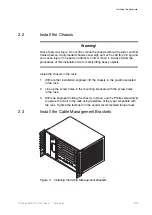
To install the left-side bracket, align it with the screw holes at the left side of
the rack and secure it to the rack with the two captive fasteners; tighten to a
maximum torque of 8.0 inch-lbs (0.9 Newton-meters).
For additional cable management, you can install another cable management
bracket at the right side of the chassis.
Note:
When you install a ride-side cable management bracket, the air filter
access will be limited only to removal from the rear of the chassis.
2.4
Connect Power and Ground Cables
The chassis ground terminal is located at the bottom-right corner of the back
panel. The ground cables must be of a size suitable for the installation, and
must be installed in accordance with the National Electrical Code (in the
United States), or the applicable local jurisdiction (outside the United States)
installation requirements.
Connect a chassis ground cable:
1.
Using a crimping tool, attach a two-hole lug to one end of the ground cable.
2.
Secure the connection with a pair of lug nuts; tighten to a maximum torque
of 15.0 inch-lbs (1.7 Newton-meters).
3.
Connect the other end of the cable to an appropriate ground point.
2.4.1
Connect DC Power Sources
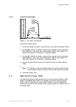
The SmartEdge 600 chassis has two terminal blocks on the rear of the chassis
labeled BATTERY A and BATTERY B for A-side and B-side DC power cables,
which provides full power redundancy. Each terminal block has a pair of 1/4-20
studs.
The A- and B-side power cables connect to separate A-side and B-side
connectors on the external fuse panel or circuit breaker panel.
The terminal studs are labeled RETURN and -48V. Each power cable must
be of a size suitable for the installation and installed in accordance with the
National Electrical Code (in the United States) or applicable local jurisdiction
(outside the United States) installation requirements.
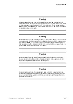
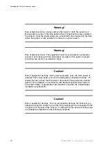
The following DC power source warnings and cautions apply when connecting
DC power sources:
24
27/153 30-CRA 119 1170/1 Uen A
|
2010-04-09
Summary of Contents for SmartEdge 600
Page 1: ...SmartEdge 600 Router Hardware Guide Release 6 3 INSTALLATION 27 153 30 CRA 119 1170 1 Uen A ...
Page 6: ...SmartEdge 600 Router Hardware Guide 27 153 30 CRA 119 1170 1 Uen A 2010 04 09 ...
Page 26: ...SmartEdge 600 Router Hardware Guide 20 27 153 30 CRA 119 1170 1 Uen A 2010 04 09 ...
Page 108: ...SmartEdge 600 Router Hardware Guide 102 27 153 30 CRA 119 1170 1 Uen A 2010 04 09 ...
Page 112: ...SmartEdge 600 Router Hardware Guide 106 27 153 30 CRA 119 1170 1 Uen A 2010 04 09 ...

