Sump Cleaner
11
The tank’s maximum capacity is, at most, 10%
above the rated capacity. A float switch in the
tank and wired into the engine ignition circuit will
shut down the engine if overfilling starts to occur.
If this happens, place the IGNITION switch in
the OFF position, and close the gas bottle valve.
Follow instructions for the discharge operation in
Paragraph 10.
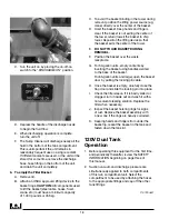
6. To return filtered chip-free coolant to the sump,
or wash down the machine, or discharge dirty
coolant into your recycling or disposal system
,
close the suction inlet ball valve V1, attach the
1-1/2" hose to the discharge port. Move the
4-way valve control lever to the vertical
(DISCHARGE) position. Open the gas bottle valve
and press the electric primer button for at least
two seconds. Turn the IGNITION KEY SWITCH
ON. Depress the discharge hose nozzle valve.
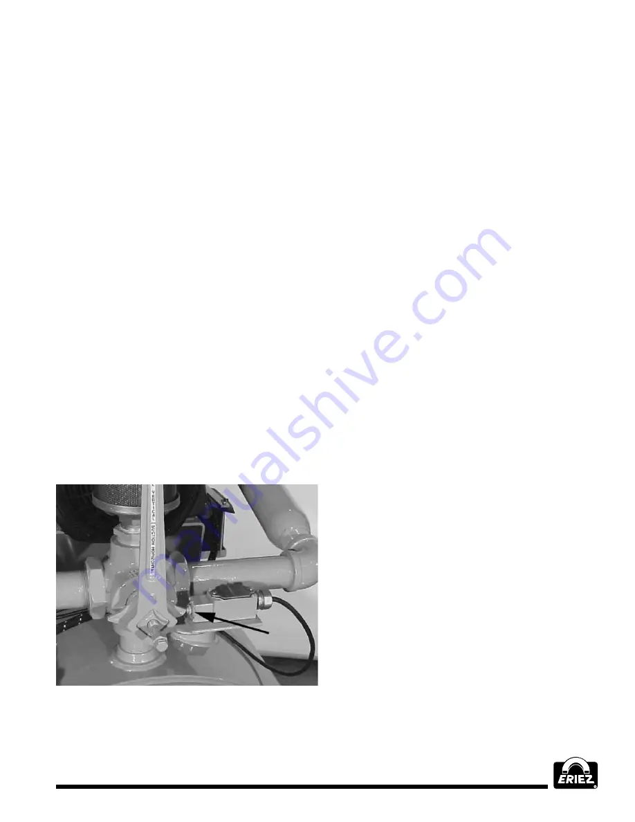
A. THE SUCTION/DISCHARGE lever must
be turned its full quarter turn to the vertical
(DISCHARGE) position in order to close a
limit switch beneath the lever (FIGURE 5).
This limit switch bypasses the float switch
needed to prevent overfilling during the
suction operation, but is not required for
discharge operation. The engine won’t start
in the discharge mode if sump cleaner tank
is full and the limit switch is not closed.
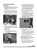
FIGuRE II-C
Limit switch under the suction/discharge lever
B. Be sure the suction inlet ball valve V1 is fully
closed before operating in the discharge mode.
C.
IMpORTANT!
Be sure the suction inlet ball
valve V1 is fully closed or fully open, depending
on the desired operation (closed-discharge,
open-suction). Failure to do so will allow
particulate to enter the valve seat and seize
the valve.
D. As soon as fluid stops passing through
the hose, release pressure by shifting the
SUCTION/DISCHARGE lever to the horizontal
(SUCTION) position. This must be done
before opening the inlet ball valve or removing
tank lid, cleanout door or drain plug. The
engine will momentarily “SPEED UP” and
then “SLOW DOWN” and begin to “labor”.
Once the engine has begun to labor, the
engine may be switched OFF. Open the ball
valve and turn OFF the gas bottle valve.
The sump cleaner will discharge all but about an
inch of fluid in the bottom of the compartment.
This is unimportant if the compartment is used for
one type of coolant only. If different coolants are
involved, remove the compartment’s drain plug
to empty it completely. Replace drain plug
after emptying.
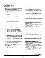
7. To fill the clean side with clean fluid:
Activate
the float switch for the compartment selected
by setting the TANK OVERFILL PROTECTION
SELECTOR SWITCH to the appropriate position
(FIGURE II-C). This float switch prevents over-
filling of the compartment and pump damage
during the suction cycle by turning off the engine’s
ignition circuit at a predetermined liquid level.
A. Install the 1-1/2" hose onto the clean side
inlet port, remove the discharge nozzle and
install that end of the hose to a recycling
system or a clean tank
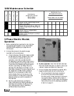
B. Place the SUCTION/DISCHARGE lever in
the horizontal (SUCTION) position. Open the
LP Gas bottle valve. Open the suction inlet
ball valve. Place choke in “ON” position.
Turn ignition key to the “START” position
while moving choke to the “OFF” position.
Release key when the engine starts and
move choke to the “OFF” position.
Summary of Contents for FJ-310A
Page 27: ...Sump Cleaner 27...


