

Sump Cleaner
15
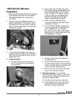
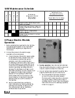
3. Discharge Operation:
To return filtered,
chip-free coolant to the machine, to wash down
the machine, or to discharge coolant into your
recycling or disposal system:
A. Close the suction inlet valve completely.
B. Close the vacuum valve completely.
C. Connect the compressed air supply line to the
compressed air inlet. (This compressed air
inlet is equipped with a preset, nonadjustable
pressure reducing regulator to lower the air
pressure to 7 PSI. A 15 PSI safety “POP-
OFF” valve in this same line acts as a back
up to prevent over-pressurizing the sump
cleaner tank). Turn on the air supply by
opening discharge valve.
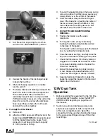
D. Depress the discharge hose nozzle handle.
E. When discharging operation is complete,
turn off the compressed air supply by
closing discharge valve and close the
discharge nozzle.
F. Discharge valve is a three-way ball valve that
will depressurize the sump cleaner tank when
fully closed. To avoid possible injury, do not
leave the sump cleaner pressurized.
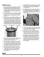
4. To empty the filter basket:
A. Remove tower lid.
B. Attach lifting device to basket rings.
CAuTION
: All components used to lift basket
(steel cable, hooks, crane, etc.) must have a
minimum capacity of 1000 pounds.
Operation Requirements
(cont.)
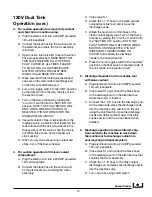
C. To avoid the basket binding in the tower
during removal, position the lifting power
source (e.g. crane) directly over the center
of the basket.
D. Hoist the basket. Keep hands and fingers
clear. If the basket is binding and unable to
lift freely, return (lower) the basket to the sump
cleaner tower. Reposition the lifting device so
that the basket exits the center of the tower.
E.
DO NOT TOuCH BASKET DuRING
REMOVAl.
F. Position the basket over the waste receptacle.
G. Standing clear, open the basket trapdoor by
pulling the locking pin cable.
H. Once the basket is empty, carefully close the
trapdoor and slide the locking pin into place.
I. Check the filter sleeve. If it is badly soiled
or clogged, turn it inside out and wash it
in a suitable cleaner. Replace filter when
necessary. (Refer to the MAINTENANCE
section of this manual.)
J. Inspect the basket hoisting rings for signs
of rust. Replace the basket with a new one
if the rings are heavily corroded.
K. Keeping hands and fingers from under the
basket lip, reseat the basket in the tank and
clamp down the tank lid.
W
e
e
k
l
y
M
o
n
t
h
l
y
6
M
o
n
t
h
s
100
H
o
u
r
s
12
M
o
n
t
h
s
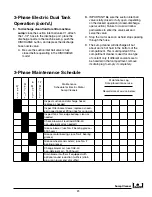
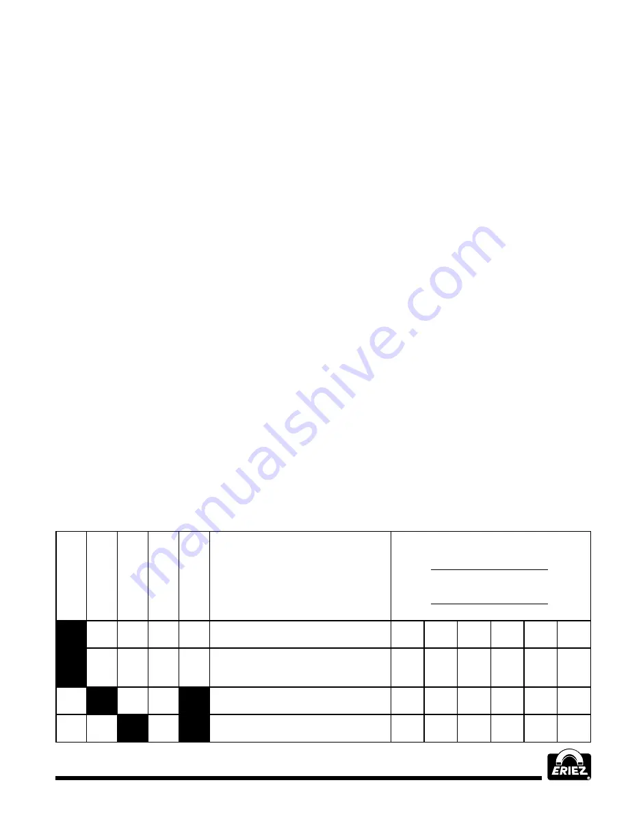
Maintenance
Schedule for
Air Venturi
Sump Cleaners
Maintenance Log
Date placed into service:
Record date of service below:
Inspect suction and discharge hoses;
replace as needed
Inspect filter basket sleeve; replace
as needed. Inspect basket lifting
rings for corrosion
Inspect tank for sludge buildup;
clean as needed
Grease wheels and casters;
use No. 2 bearing grease
Summary of Contents for FJ-310A
Page 27: ...Sump Cleaner 27...