

20
W
e
e
k
l
y
M
o
n
t
h
l
y
6
M
o
n
t
h
s
12
M
o
n
t
h
s
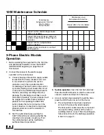
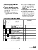
Maintenance
Schedule for 120-Volt
Electric Motor
Sump Cleaner
Maintenance Log
Date placed into service:
Record date of service below:
Inspect suction and discharge hoses;
replace as needed
Inspect filter basket sleeve; replace as
needed. Inspect basket lifting rings for
corrosion
Inspect tank for sludge buildup;
clean as needed
Grease wheels and casters; use No. 2
bearing grease
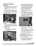
120V Maintenance Schedule
1. Before operating this equipment for the first time,
and periodically thereafter, review the SAFETY
INFORMATION beginning on page three of
this manual.
2. Connect the cleaner to the electric supply
specified on the control panel.
A. Correct phasing of the electric supply outlets
is essential. The Sump Cleaner motor runs
in one direction to perform the suction
operation, and in the opposite direction
for discharge. The float switch in the suction
cycle relay holding circuit causes this circuit
to drop out at a predetermined liquid level in
the tank, preventing overfilling and pump
damage. The discharge circuit has no such
float switch; therefore, the sump cleaner must
be plugged into outlets that are uniformly
phased, so that operating the SUCTION
button rotates the motor and pump in the
correct direction. Connection to improperly
phased outlets can void the warranty on
this machine.
B. Test the outlet phasing by pushing the
SUCTION button and verifying whether the
cleaning tool is actually vacuuming. If not,
the outlet phasing must be modified by
authorized service personnel.
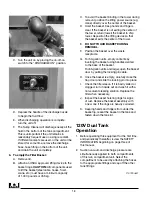
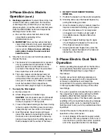
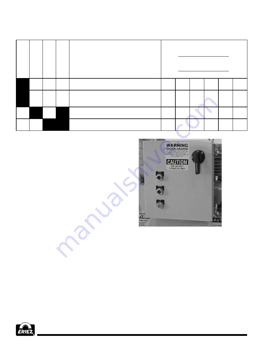
3-phase Electric Models
Operation
3. Suction operation
: Open the inlet ball valve fully.
Press the SUCTION button to start the motor and
vacuum coolant and chips from the sump.
4. As soon as fluid stops passing through the hose,
press the STOP button to turn off the motor.
A. The compartment’s maximum capacity is,
at most, 10% above the rated capacity.
The float switch, located near the component
tank suction fitting, will shut off the motor if
overfilling starts to occur. If this should happen,
follow instructions for the discharge operation
in item 5 on page 17.
Summary of Contents for FJ-310A
Page 27: ...Sump Cleaner 27...