background image

Sump Cleaner

21

3-phase Electric Models
Operation 

(cont.)

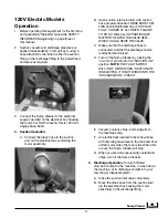
5.  Discharge operation

: To return filtered chip-free 

coolant to the sump, wash down the machine, 
or discharge dirty coolant into your recycling or 
disposal system, close the suction inlet ball valve. 
Push the DISCHARGE button and depress the 
discharge hose nozzle valve.  
A.  Be sure the suction inlet ball valve is fully  
 

closed before operating in the  


DISCHARGE mode! 

B. 

IMpORTANT

! Be sure the suction inlet ball  


valve is fully closed or fully open, depending  


on the desired operation (closed-discharge,  

 open-suction). 

Failure to do so will allow  


particulates to enter the valve seat and  


seize the valve.

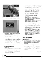
6.  Stop the motor as soon as fluid stops passing 

through the hose. 
A.  The cleaner is to be adjusted and/or repaired  
 

only by qualified service personnel. If these  


personnel need more information than is  


provided in this manual, they should contact  


Eriez HydroFlow at 814-520-8540

.


B.  The sump cleaner will discharge nearly all  
 

of the fluid in the bottom of the tank. This is  


unimportant if the compartment is used for  


one type of coolant only. If different coolants  


are to be handled in that compartment,  


remove its drain plug to empty it completely.

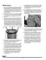
7.  To empty the filter basket: 

A.  Remove tower lid. 
B.  Attach lifting device to basket rings.  
 

CAuTION

: All components used to lift basket  


(steel cable, hooks, crane, etc.) must have a  


minimum capacity of 1000 pounds. 

C.  To avoid the basket binding in the tower during  
 

removal, position the lifting power source (e.g.  


crane) directly over the center of the basket. 

D.  Hoist the basket. Keep hands and fingers  
 

clear. If the basket is not exiting the center of  


the tower, return (lower) basket to the sump  


cleaner tower. Reposition the lifting device so  


that the basket exits the center of the tower. 

E. 

DO NOT TOuCH BASKET DuRING  

 REMOVAl.


F.  Position the basket over the waste receptacle. 
G.  Standing clear, open the basket trapdoor by  
 

pulling the locking pin cable. 

H.  Once the basket is empty, carefully close the  
 

trapdoor and slide the locking pin into place. 

I.  Check the filter sleeve. If it is badly soiled  
 

or clogged, turn it inside out and wash it  


in a suitable cleaner. Replace filter when  

 necessary. 


J.  Inspect the basket hoisting rings for signs  
 

of rust. Replace the basket with a new one  


if the rings are heavily corroded. 

K.  Keeping hands and fingers from under the  
 

basket lip, reseat the basket in the tank and  


clamp down the tank lid.

1.  Before operating this equipment for the first time, 

and periodically thereafter, review the SAFETY 
INFORMATION beginning on page three of  
this manual.

2.  Suction vacuum and discharge pressure are 

simultaneously applied to both compartments  
of this twin compartment unit. Select the 
compartment to be used by attaching the hoses 
to the appropriate fittings and cap off the other 
tank fittings.

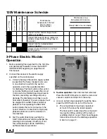
3.  For suction operation: Activate the float switch for 

the compartment selected by setting the TANK 
OVERFILL PROTECTION SELECTOR to the 
corresponding position. This float switch prevents 
overfilling of the compartment and pump damage 
during the suction cycle, by causing the suction 
holding circuit to drop out at a predetermined tank 
liquid level.

4.   Connect the cleaner to the electric supply 

specified on the control panel. 
A.  Correct phasing of the electric supply outlets  
 

is essential. The sump cleaner’s motor runs in  


one direction to perform the suction operation  


and in the opposite direction for discharge.    

3-phase Electric Dual Tank
Operation

Summary of Contents for FJ-310A

Page 1: ...eaner 1 Installation Operation and Maintenance Instructions FJ 310A Sump cleaner ERIEZ MAGNETICS HEADQUARTERS 2200 ASBURY ROAD ERIE PA 16506 1402 U S A WORLD AUTHORITY IN SEPARATION TECHNOLOGIES P C 7...

Page 2: ...E FEATURES 4 SUMP CLEANER WARRANTY 5 ASSEMBLY 6 OPERATING TIPS 7 LP MODELS 8 LP GAS DUAL TANK MODELS OPERATION 10 AIR OPERATED MODELS 11 AIR VENTURI DUAL TANK OPERATION 15 120V MODELS 13 120V DUAL TAN...

Page 3: ...fter operating engine driven units LP gas or gasoline in the discharge mode and before stopping engine turn the SUCTION DISCHARGE lever to the SUCTION position The engine will SPEED UP momentarily and...

Page 4: ...eak proof round cleanout doors are faster and easier to remove and replace than the oval internal manholes used by other manufacturers The thick pliable gasket bonded to the cleanout door virtually el...

Page 5: ...turers for purpose of pursuing warranty claims or making service arrangements or any other purpose Copies of such third party sub assembly manufacturers specific warranty information will be shipped w...

Page 6: ...ake out the following items A Filter basket factory assembled with sleeve B Discharge hose with nozzle C Suction hose D Cleaning tool E Spare filter sleeve or filter bags F LP bottle brackets on LP mo...

Page 7: ...th water soluble coolants and another for use with cutting oils If you must use one unit for both the sump cleaner must be thoroughly cleaned when switching products If at all possible purchase a filt...

Page 8: ...n Release key when the engine starts and move choke to the OFF position Figure 3 Pull out for CHOKE Figure 4 Turn key to START 5 Vacuum coolant and chips from the sump 6 As soon as fluid stops passing...

Page 9: ...of fluid in the bottom of the compartment This is unimportant if the compartment is used for one type of coolant only If different coolants are involved remove the compartment s drain plug to empty it...

Page 10: ...suction and discharge hoses to the proper fittings on that tank compartment Cap off all other fittings 5 For dirty fluid suction operation Activate the Pull out for CHOKE Turn key to START float swit...

Page 11: ...d operation closed discharge open suction Failure to do so will allow particulate to enter the valve seat and seize the valve D As soon as fluid stops passing through the hose release pressure by shif...

Page 12: ...mit switch bypasses the float switch needed to prevent overfilling during the suction operation but is not required for discharge operation The engine won t start in the discharge mode if sump cleaner...

Page 13: ...eded Inspect tank for sludge buildup clean as needed Check blower oil level add SAE 40 non detergent oil as needed Grease blower use 2 bearing grease 500 hours Check engine air filter replace as neede...

Page 14: ...uld be taken out of service immediately until the parts are repaired or replaced DO NOT eliminate the safety release valve or replace it with a release valve rated higher than 15 PSI DO NOT reset the...

Page 15: ...tower during removal position the lifting power source e g crane directly over the center of the basket D Hoist the basket Keep hands and fingers clear If the basket is binding and unable to lift free...

Page 16: ...harge nozzle D Attach the nozzle end of this hose to the clean coolant supply tank Turn on the compressed air and reattach the discharge nozzle to the hose when full Close vacuum valve V2 The compress...

Page 17: ...ON position NOTE THE FLOAT SWITCH WILL ONLY WORK WHEN SUCTION ON IS SELECTED IT IS NOT WIRED INTO THE DISCHARGE ON CIRCUIT 3 Connect the Sump Cleaner to the electrical supply specified on the electri...

Page 18: ...eposition the lifting device so that the basket exits the center of the tower E DO NOT TOUCH BASKET DURING REMOVAL F Position the basket over the waste receptacle G For 50 gallon units empty contents...

Page 19: ...containing the motor assembly C Close valve S 1 D Attach the 1 1 2 hose to the clean coolant compartment inlet port and remove the discharge nozzle F Attach the nozzle end of this hose to the clean c...

Page 20: ...cuit to drop out at a predetermined liquid level in the tank preventing overfilling and pump damage The discharge circuit has no such float switch therefore the sump cleaner must be plugged into outle...

Page 21: ...center of the tower return lower basket to the sump cleaner tower Reposition the lifting device so that the basket exits the center of the tower E DO NOT TOUCH BASKET DURING REMOVAL F Position the bas...

Page 22: ...valve V1 attach the 1 1 2 hose to the discharge port place the discharge nozzle in the machine sump push the DISCHARGE button and depress the discharge hose nozzle valve A Be sure the suction inlet ba...

Page 23: ...ce Schedule 9 To discharge clean fluid to refill a machine sump close the suction inlet ball valve V1 attach the 1 1 2 hose to the discharge port place the discharge nozzle in the machine sump push th...

Page 24: ...of the tank Remove these periodically by opening the drain plug and with the filter basket out of the sump cleaner flush the tank with a water hose 6 Periodically while the basket is out of the tank c...

Page 25: ...Check for obstructions physically remove 2B Check for cracks or holes replace 3 Air leakage 3 Check all hose connections for tightness make sure female quick disconnect fittings have gaskets in place...

Page 26: ...l coolant supplier for corrective action LP Engine Stalls During Discharge or Suction 1 Engine 1 Check engine RPM adjust as necessary 2 Regulator 2 Pressure or vacuum regulator could be out of adjustm...

Page 27: ...Sump Cleaner 27...

Page 28: ...0 345 4946 Fax 814 838 4960 International Fax 814 833 3348 Web Site http www eriez com e mail eriez eriez com Manufacturing Facilities AUSTRALIA BRAZIL CANADA CHINA INDIA JAPAN MEXICO SOUTH AFRICA UNI...

Reviews: