


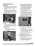
4
Operator Safety and
Convenience Features
Safety Features
Although sump cleaners are inherently safe machines,
they pose the potential for hand and finger injury
when the operator removes the filter basket from the
unit to empty it of chips and sludge. For this reason,
Eriez HydroFlow has two safety features which are
unique to their Sump Cleaners.
Filter basket safety guides automatically center
the filter basket within the unit’s basket support
tower as it is being hoisted out of the machine.
This eliminates the need for the operator to physically
guide the heavy, full basket as it is being elevated and
significantly reduces the opportunity for the operator
to receive hand injuries.
Basket “trapdoor” release cables enable the operator
to empty the filter basket (the basket can hold up to
800 pounds of chips) from a safe distance without
the need for special tools. The basket is removed
from the unit, positioned over a chip hopper or similar
receptacle, and the contents are released through the
basket bottom by the operator opening the trapdoor
with a sharp pull on the release cable. During the
entire operation, the operator is a safe distance away.
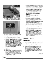
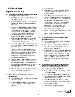
Convenience Features
Low rolling resistance, high maneuverability design:
Sump Cleaners feature high impact, fiber reinforced,
hard plastic casters and wheels for low rolling
resistance, whether the unit is empty or full. The
standard wheel configuration places the main wheels
in the unit’s middle and swivel casters on each end
for high maneuverability. A Sump Cleaner pivots
within its own length while “tricycle gear” units swing
in double their length.
Clamped basket lids make lid removal and
replacement much faster and easier than it is with
the screw clamps used on other makes of sump
cleaners. Easy Lift Chip Basket Lid allows the lid to
easily and safely lift up and out of the way to allow
access to the chip basket.
External, leak-proof, round cleanout doors are faster
and easier to remove and replace than the oval,
internal “manholes” used by other manufacturers.
The thick, pliable gasket bonded to the cleanout
door virtually eliminates leaks.
Forklift truck brackets are standard on all “push-
around” Sump Cleaners so that the unit can be safely
and easily picked up and moved long distances.
17. This equipment is to be operated and maintained
by authorized personnel only.
18. MAGNESIUM CHIPS OR DISSIMILAR METALS
In the presence of water, magnesium can release
highly flammable hydrogen gas. In the proper
proportions with air, it can be explosive. When
a Sump Cleaner is used on a metalworking
fluid application generating magnesium chips,
certain precautions must be taken to ensure
that any hydrogen gas is dissipated into the
atmosphere and to make sure the hydrogen
does not accumulate in the Sump Cleaner.
This is accomplished by promptly removing
any magnesium chips from the sump cleaner
basket. Also, a maintenance schedule should
be established by the customer that would
eliminate buildup of sludge in the bottom of
the Sump Cleaner. Finally, the unit should be
stored in a clean condition with basket empty of
chips, the sump cleaner tower lid removed, the
coolant discharge nozzle(s) removed, and hoses
opened to the atmosphere (on single and twin
compartment units). Taking these precautions
will minimize the risk of hydrogen gas generation
and accumulation.
On an application where dissimilar metals are
machined, there is a chance for spontaneous
combustion to occur. Typically, metalworking
facilities that machine various metals are aware
of this and may have experienced problems in
chip hoppers due to the presence of two or more
metals, water, and tramp oil.
The precautions mentioned in the previous
paragraph will minimize or eliminate the potential
for spontaneous combustion.
19. The cleaner is to be adjusted and/or repaired only
by qualified service personnel. If these personnel
need more information than is provided in this
manual, they should contact Eriez HyrdroFlow
at 814-520-8540.
Safety Information
(cont.)
Summary of Contents for FJ-310A
Page 27: ...Sump Cleaner 27...


