


8
1. Before operating this equipment for the first time,
and periodically thereafter, review the SAFETY
INFORMATION beginning on page three of
this manual.
2. The standard sump cleaner LP gas engine is
equipped with LIQUID WITHDRAWAL regulators,
for use with either LIQUID or VAPOR
WITHDRAWAL LP GAS BOTTLES.
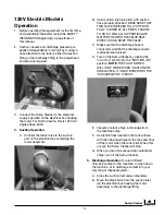
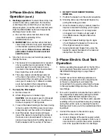
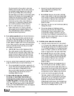
3. Suction and discharge cycles are controlled by a
four-way valve in the piping from the SUCTION/
DISCHARGE pump to the tank. Placing the
valve’s control lever in the horizontal position
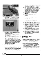
selects the SUCTION mode (FIGURE 1). Moving
the lever a quarter turn to the vertical position
selects the DISCHARGE mode (FIGURE 2).
lp Gas Models
Operation
FIGuRE 1
Suction/Discharge lever - SUCTION position
FIGuRE 2
Suction/Discharge lever - DISCHARGE position
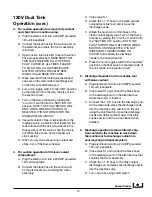
4. Place the SUCTION/DISCHARGE lever in the
horizontal (SUCTION) position. Open the LP Gas
bottle valve. Open the suction inlet ball valve.
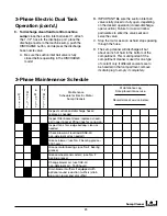
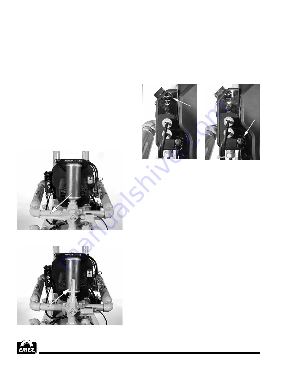
Place choke in “ON” position (FIGURE 3).
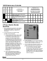
Turn ignition key to the “START” position
(FIGURE 4) while moving choke to the “OFF”
position. Release key when the engine starts
and move choke to the “OFF” position.
FIGuRE 3
Pull out for CHOKE
FIGuRE 4
Turn key to START
5. Vacuum coolant and chips from the sump.
6. As soon as fluid stops passing through the hose,
stop the engine by turning the IGNITION switch
OFF. Close the gas bottle valve. This valve must
always be closed when engine is not running.The
tank’s maximum capacity is, at most, 10% above
the rated capacity. A float switch in the tank and
wired into the engine ignition circuit will shut down
the engine if overfilling starts to occur. If this
happens, place the IGNITION switch in the OFF
position, and close the gas bottle valve. Follow
instructions for the discharge operation in Item 7.
7. To return filtered chip-free coolant to the
sump, or wash down the machine, or
discharge dirty coolant into your recycling
or disposal system,
close the suction inlet ball
valve. Move the four-way valve control lever to
the vertical (DISCHARGE) position. Open the
gas bottle valve and place choke in “ON” position.
Turn ignition key to the “START” position while
moving choke to the “OFF” position. Release key
when the engine starts and move choke to the
“OFF” position. Depress the discharge hose
nozzle valve.
Summary of Contents for FJ-310A
Page 27: ...Sump Cleaner 27...


