
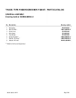
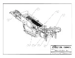
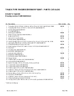
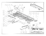
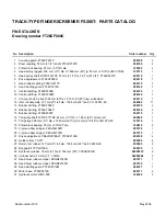
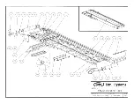
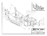
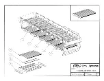
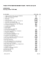
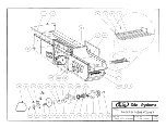
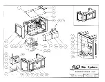


TRACK-TYPE FINGERSCREENER FS206T: PARTS CATALOG
REJECT STACKER
Drawing number SAB10A0000A-0
No Description
Order number
Qty
1
Tail pulley, 305 mm (12") dia. x 1600 mm (63") lg, 75 mm (2 15/16") shaft, XTH30, XTB30
125716
1
2
Tail pulley shaft, 75 mm (2 15/16") x 1.88 m (74 1/8"), SAB10A0061P-0
-
1
3
Rubber skirting SAB10A0204P-0
-
1
4
Pin, SAB10A0370A-0
-
2
5
Retaining pin DA5050-14
105961
2
6
Reject conveyor side plate, SAB10A0070A-0
-
2
7
Guide rollers, 10-371
205384
4
8
Idler roll, 127 mm (5") roll dia.
125714
8
9
Rubber skirting, SAB10A0002N-0
-
2
10
Head Pulley lagged, 305 mm (12") dia. X 1600 mm (63") lg, 87 mm (3 7/16") shaft, XTH35, XTB35
125715
1
11 Head pulley shaft, 87 mm (3 7/16") x 2.096 m (82 1/2"), SAB10A0051P-0
-
1
12 Pillow block bearing, 87 mm (3 7/16") dia.
125722
2
13 Steel coupling, 57 mm (2 1/4") shaft + 49 mm (1 15/16") shaft, SAB10A0701P-0
-
2
14 Dowell pin*
203016
4
15 Coupling guard, SAB10A0401P-0
-
2
16 Motor base, SAB10A0410A-0
-
2
17 Hydraulic motor, OMV-500
124320
2
18 Belt beater, SAB10A0510A-0
-
1
19 Belt beater support, SAB10A550A-0
-
1
20 Flange bearing
145282
2
21 Plastic support, (1372mm) (54"), SAB10A3600A-0
-
6
22 Anti-nip guard, SAB10A0602P-0
-
1
23 Return roll, rubber, 127 mm (5") roll dia., 1524 mm (60") belt
205385
1
24 V-plow rubber scraper, PECH62103N
201975
1
25 V-plow rubber scraper, PECH62102N
201974
1
26 Plastic support, 1473 mm (58"), SAB10A3500A-0
-
14
27 Plastic bar, (51mm X 51mm x 1372 mm) (2" X 2" X 54"), SAB10A3001P-0
-
18
28 Plastic support, 1067 mm (42"), SAB10A2500A-0
-
12
29 Rubber damper, 19 mm (3/4") x 51 mm (2") x 1067 mm (42") lg
125720
12
30 Support pin, FT26CR903P
206108
1
31 Plastic bar, (51mm X 51mm x 1066 mm) (2" X 2" X 42")
125719
12
32 Pillow block bearing, 62 mm (2 15/16") dia.
144812
2
33 Conveyor belt, 3 plies, 1524 mm (60") x 15,37 m (605") lg vulcanized, SAB10A0001N-0
-
1
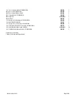
* Not shown on drawing
Serial number 3010
May 2006
Summary of Contents for Fingerscreener 206T
Page 73: ......
Page 79: ......
Page 81: ......
Page 83: ......
Page 85: ......
Page 87: ......
Page 90: ......
Page 93: ......
Page 96: ......
Page 100: ......
Page 102: ......
Page 103: ......
Page 104: ......
Page 105: ......
Page 106: ......
Page 107: ......
Page 108: ......
Page 109: ......
Page 110: ......
Page 111: ......
Page 112: ......
Page 113: ......
Page 114: ......
Page 115: ......
Page 116: ......
Page 117: ......
Page 118: ......
Page 119: ......
Page 120: ......
Page 131: ...7C 13 3 B 31 C 142 H6 HU VS MH HYDROMATIK A2FE 125 61W PZL100 MT713C033 23 06 2006 ...


