7 Acceptance/Protection Function Test Guide
7-50
L-PRO 4000 User Manual
D02706R02.30
25/27/59 Sync
Check Test
Note: Three or four voltage sources are required for this test.
The relay will create the positive sequence sync check voltage out of the sin-
gle-phase auxiliary voltage input depending on which phase is injected.
Settings
• Maximum voltage: 70 V sec. (Maximum Positive Sequence voltage)
• Minimum voltage: 40 V sec. (Minimum Positive Sequence voltage)
• Angle Difference: 20 degrees
• Time Delay: 200 milliseconds
• Dead Main Live Aux. (DMLA): Enable
• Live Main Dead Aux. (LMDA): Enable
• Dead Main Dead Aux. (DMDA): Enable
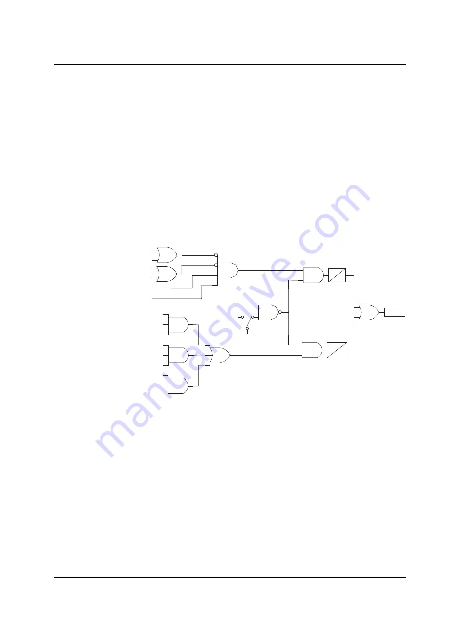
Figure 7.33: Synchronism Check Logic (25/27/59)
27 Vmain (Positive Seq, 20 V Fixed)
216
213
Dead Main-Dead Sync Enabled
59 Vmain (Positive Seq, 20 V Fixed)
27 Vsync (Positive Seq, 20 V Fixed)
215
Live Main-Dead Sync Enabled
27 Vmain (Positive Seq, 20 V Fixed)
59 Vsync (Positive Seq, 20 V Fixed)
214
Dead Main-Live Sync Enabled
27 Vmain (Positive Seq)
208
27 Vaux (Positive seq)
59 Vmain (Positive seq)
209
59 Vsync (Positive seq)
210
|VmainAngle-VauxAngle| < Setting
25 C (Sync Check) Enabled
T
0
25ms
0
211
212
52a Main
52a Aux
(+)
217
Out 10
218
27 Vsync (Positive Seq, 20 V Fixed)
Summary of Contents for L-PRO 4000
Page 1: ...L PRO 4000 Transmission Line Protection Relay User Manual Version 2 3 Rev 0...
Page 2: ......
Page 4: ......
Page 8: ......
Page 10: ......
Page 14: ......
Page 40: ......
Page 50: ......
Page 116: ......
Page 146: ......
Page 218: ......
Page 252: ...Appendix B IED Settings and Ranges Appendix B 34 L PRO 4000 User Manual D02706R02 30...
Page 260: ......
Page 270: ......
Page 302: ......
Page 308: ......
Page 310: ......
Page 312: ......


