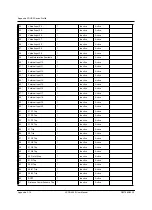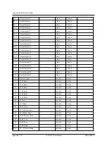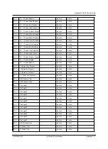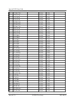
Appendix F DNP3 Device Profile
Appendix F-12
L-PRO 4000 User Manual
D02706R02.30
Capabilities and
Current
Settings for
Device
Database
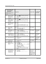
The following tables identify the capabilities and current settings for each
DNP3 data type. Each data type also provides a table defining the data points
available in the device, default point lists configuration and a description of
how this information can be obtained in case of customized point configura-
tion.
2.1 Single-Bit Binary Inputs
Static (Steady-State) Group Number: 1
Event Group Number: 2
Capabilities
Current Value
If configurable,
list methods
2.1.1
Static Variation reported
when variation 0
requested:
Variation 1 - Single-bit Packed format
Variation 2 - Single-bit with flag
Based on point Index (add column to table
below)
2.1.2
Event Variation
reported when variation
0 requested:
Variation 1 - without time
Variation 2 - with absolute time
Variation 3 - with relative time
Based on point Index (add column to table
below)
2.1.3
Event reporting mode:
Only most recent
All events
2.1.4
Binary Inputs included
in Class 0 response:
Always
Never
Only if point is assigned to Class 1, 2, or 3
Based on point Index (add column to table
below)
L-PRO Offliner
2.1.5
Definition of Binary
Input Point List:
Fixed, list shown in table below
Configurable
Other, explain_____________________
Complete list is
shown in the
table below;
points excluded
from the default
configuration are
marked with ‘*’
L-PRO Offliner
Notes
1. Binary Inputs are scanned with 1 ms resolution.
2. Binary Input data points are user selectable; the data points avail-
able in the device for any given Binary Input point selection can be
obtained through the L-PRO Offliner software (see SCADA Setting
Summary).
Summary of Contents for L-PRO 4000
Page 1: ...L PRO 4000 Transmission Line Protection Relay User Manual Version 2 3 Rev 0...
Page 2: ......
Page 4: ......
Page 8: ......
Page 10: ......
Page 14: ......
Page 40: ......
Page 50: ......
Page 116: ......
Page 146: ......
Page 218: ......
Page 252: ...Appendix B IED Settings and Ranges Appendix B 34 L PRO 4000 User Manual D02706R02 30...
Page 260: ......
Page 270: ......
Page 302: ......
Page 308: ......
Page 310: ......
Page 312: ......


