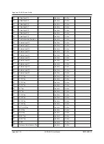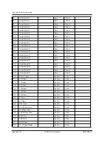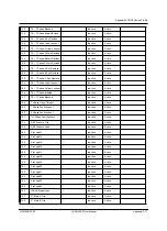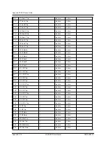
Appendix F DNP3 Device Profile
D02706R02.30
L-PRO 4000 User Manual
Appendix F-21
NOTES
1. Binary Outputs are scanned with 500 ms resolution.
2. Events are not supported for Binary Outputs (group 10), but most of Binary
Output points can be mapped to Binary Inputs (group 2) with full Event and Class
Data support. See L-PRO Offliner/DNP Configuration/Point Map screen for com-
plete point lists and configuration options.
3. Virtual Inputs (default Binary Output points 94-123) can be used to control re-
lay output contacts. See L-PRO Offliner/Setting Group X/Output Matrix screen
for configuration options.
4. Binary Output data points are user selectable; the data points available in the
device for any given Binary Output point selection can be obtained through the
L-PRO Offliner software (see SCADA Setting Summary).
Supported Control Operations
Default Class
Assigned to Events
(1, 2, 3 or none)
Point Index
Name
Select/Operate
Direct Operate
Direct Operate - No Ack
Pulse On / NUL
Pulse Off
Latch On / NUL
Latch Off / NUL
Trip
Close
Count > 1
Cancel Currently Running Operation
Name for
State when
value is 0
Name for
State when
value is 1
Change
Command Description
0
Output contact 1
-
-
-
-
-
-
-
-
-
-
-
Open
Closed
None
None
1
Output contact 2
-
-
-
-
-
-
-
-
-
-
-
Open
Closed
None
None
2
Output contact 3
-
-
-
-
-
-
-
-
-
-
-
Open
Closed
None
None
3
Output contact 4
-
-
-
-
-
-
-
-
-
-
-
Open
Closed
None
None
4
Output contact 5
-
-
-
-
-
-
-
-
-
-
-
Open
Closed
None
None
5
Output contact 6
-
-
-
-
-
-
-
-
-
-
-
Open
Closed
None
None
6
Output contact 7
-
-
-
-
-
-
-
-
-
-
-
Open
Closed
None
None
7
Output contact 8
-
-
-
-
-
-
-
-
-
-
-
Open
Closed
None
None
8
Output contact 9
-
-
-
-
-
-
-
-
-
-
-
Open
Closed
None
None
9
Output contact 10
-
-
-
-
-
-
-
-
-
-
-
Open
Closed
None
None
10
Output contact 11
-
-
-
-
-
-
-
-
-
-
-
Open
Closed
None
None
11
Output contact 12
-
-
-
-
-
-
-
-
-
-
-
Open
Closed
None
None
12
Output contact 13
-
-
-
-
-
-
-
-
-
-
-
Open
Closed
None
None
13
Output contact 14
-
-
-
-
-
-
-
-
-
-
-
Open
Closed
None
None
14
Virtual Input 1
Y
Y
Y
Y
-
Y
Y
-
-
-
-
Inactive
Active
None
None
Pulse duration fixed
at 1 s
15
Virtual Input 2
Y
Y
Y
Y
-
Y
Y
-
-
-
-
Inactive
Active
None
None
Pulse duration fixed
at 1 s
16
Virtual Input 3
Y
Y
Y
Y
-
Y
Y
-
-
-
-
Inactive
Active
None
None
Pulse duration fixed
at 1 s
17
Virtual Input 4
Y
Y
Y
Y
-
Y
Y
-
-
-
-
Inactive
Active
None
None
Pulse duration fixed
at 1 s
18
Virtual Input 5
Y
Y
Y
Y
-
Y
Y
-
-
-
-
Inactive
Active
None
None
Pulse duration fixed
at 1 s
Summary of Contents for L-PRO 4000
Page 1: ...L PRO 4000 Transmission Line Protection Relay User Manual Version 2 3 Rev 0...
Page 2: ......
Page 4: ......
Page 8: ......
Page 10: ......
Page 14: ......
Page 40: ......
Page 50: ......
Page 116: ......
Page 146: ......
Page 218: ......
Page 252: ...Appendix B IED Settings and Ranges Appendix B 34 L PRO 4000 User Manual D02706R02 30...
Page 260: ......
Page 270: ......
Page 302: ......
Page 308: ......
Page 310: ......
Page 312: ......


