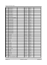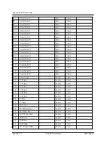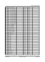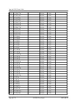
Appendix F DNP3 Device Profile
D02706R02.30
L-PRO 4000 User Manual
Appendix F-25
NOTES
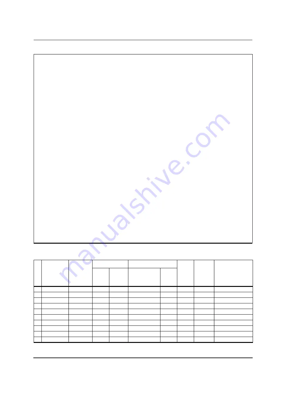
1. Analog Inputs are scanned with 500 ms resolution.
2. Nominal values in calculations for the following table are based on 69V sec-
ondary voltage * PT ratio for voltage channels, and either 1 A or 5A secondary
current * CT ratio for current channels dependent upon the format of CT installed
in the L-PRO.
3. Analog Input data points are user selectable; the data points available in the
device for any given Analog Input point selection can be obtained through the L-
PRO Offliner software (see SCADA Setting Summary).
4. When a fault location event is available, Binary Input Fault Information Avail-
able (default point index 39) is asserted while there are still fault location events
in the buffer (size 100). When a Pulse or Latch is received for the Binary Output
Get Next Fault Event (default point index 44, previous state is not important),
fault event information is put into the Analog Inputs. If there is no fault location
event available when the Binary Output is pulsed, the fault type is set to zero.
Not all fault location events are reported trough DNP. In a burst of fault locations
from a fault, only the first processed event is available through DNP, all other
events within the following 100 ms interval are ignored. Outside 100 ms from the
processed fault location event, the system accepts another fault location event
and performs the same filtering. In addition, only fault location events generated
by trip elements are available.
The following bitmap id used for the fault information Type points:
0x0001 Phase A
0x0002 Phase B
0x0004 Phase C
0x0008 Ground
Transmitted Value
a
Scaling
b
Point Index
Name
Default Class
Assigned to
Events
(1, 2, 3 or none)
Minimum
Maximum
d
Multiplier
(default/ (range))
Offset
Units
Resolution
c
(default/
maximal)
Description
0
Line Va Magnitude
2
0
Configurable 0.1 / (0.00001- 1.0)
0.0
kV
0.1 / 0.00001
1
Line Va Angle
2
-18,000
18,000
0.1 / (0.01 - 1.0)
0.0
Degrees
0.1 / 0.01
2
Line Vb Magnitude
2
0
Configurable 0.1 / (0.00001- 1.0)
0.0
kV
0.1 / 0.00001
3
Line Vb Angle
2
-18,000
18,000
0.1 / (0.01 - 1.0)
0.0
Degrees
0.1 / 0.01
4
Line Vc Magnitude
2
0
Configurable 0.1 / (0.00001- 1.0)
0.0
kV
0.1 / 0.00001
5
Line Vc Angle
2
-18,000
18,000
0.1 / (0.01 - 1.0)
0.0
Degrees
0.1 / 0.01
6
Line Ia Magnitude
2
0
Configurable 1.0 / (0.01 - 1000)
0.0
A
1.0 / 0.01
7
Line Ia Angle
2
-18,000
18,000
0.1 / (0.01 - 1.0)
0.0
Degrees
0.1 / 0.01
8
Line Ib Magnitude
2
0
Configurable 1.0 / (0.01 - 1000)
0.0
A
1.0 / 0.01
9
Line Ib Angle
2
-18,000
18,000
0.1 / (0.01 - 1.0)
0.0
Degrees
0.1 / 0.01
Summary of Contents for L-PRO 4000
Page 1: ...L PRO 4000 Transmission Line Protection Relay User Manual Version 2 3 Rev 0...
Page 2: ......
Page 4: ......
Page 8: ......
Page 10: ......
Page 14: ......
Page 40: ......
Page 50: ......
Page 116: ......
Page 146: ......
Page 218: ......
Page 252: ...Appendix B IED Settings and Ranges Appendix B 34 L PRO 4000 User Manual D02706R02 30...
Page 260: ......
Page 270: ......
Page 302: ......
Page 308: ......
Page 310: ......
Page 312: ......


