Appendix L L-PRO Setting Example
Appendix L-2
L-PRO 4000 User Manual
D02706R02.30
L.1 Switching Setting Groups
The user can program a total of 16 Group Logic statements per setting group
to cause a setting change from one group to another. Create settings using the
Offliner
setting software or by using the Terminal Mode.
Some common uses for setting groups might be cold load pickup, Zone 1 and/
or Zone 2 reach extension for phase and ground distance elements, zero
sequence source increase or decrease.
An example of pulsing an external input and an example of a solid initiate to
activate setting group changes are shown below.
Using One
External Input
to Toggle
Setting Group
Use one external input connected to a SCADA output contact to toggle be-
tween 2 or more setting groups. In this example we connect external input one
(EI 1) to the SCADA control output contact and switch between group 1 and
group 2. If the user wanted to switch through all setting groups, group logic 2
would switch to setting group 3, and so forth. If the contact input to switch set-
ting groups becomes welded shut or the SCADA system has a problem, the re-
lay will only switch to the new logic and stay in that logic until the input has
been de-energized for the ProLogic pickup delay, which was set to 10 seconds.
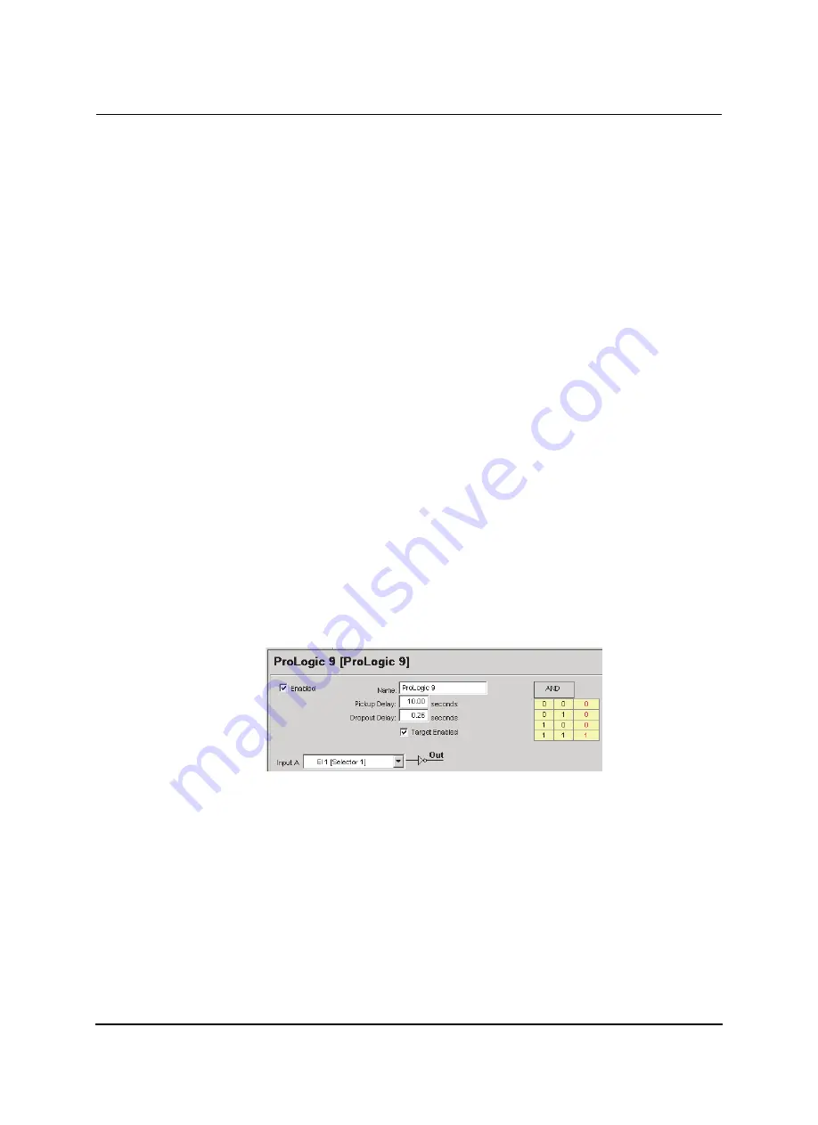
Setting Group 1 – Logic Statements
When setting group one becomes active either through a setting group change
or is the default group after relay power up, ProLogic 9 becomes high after the
10.00 second delay, if EI 1 is low. ProLogic 9 is set for a 0.26 second dropout
time; to be used with ProLogic 10 dropout timer allowing for the slower pro-
cessing thread where Group Logic is processed and providing a definite timed
pulse to the group logic.
Figure L.1: ProLogic 9
Summary of Contents for L-PRO 4000
Page 1: ...L PRO 4000 Transmission Line Protection Relay User Manual Version 2 3 Rev 0...
Page 2: ......
Page 4: ......
Page 8: ......
Page 10: ......
Page 14: ......
Page 40: ......
Page 50: ......
Page 116: ......
Page 146: ......
Page 218: ......
Page 252: ...Appendix B IED Settings and Ranges Appendix B 34 L PRO 4000 User Manual D02706R02 30...
Page 260: ......
Page 270: ......
Page 302: ......
Page 308: ......
Page 310: ......
Page 312: ......


