4 Protection Functions and Specifications
4-28
L-PRO 4000 User Manual
D02706R02.30
Summary of
Trip and
Reclose
Schemes
Three-Phase Trip and Reclose Scheme Setting
Provides 3-phase tripping for any type of line fault with up to four (4) shots of
reclosure possible.
Single-Phase Trip and Reclose Scheme Setting
This scheme allows one shot of trip and reclose if the fault is single phase in
nature. Multiple Phase line faults will 3-phase trip and lockout. Single phase
faults occurring at a frequency less than TD5 reset time will result in 3-phase
trip and lockout after first attempted reclose.
Single-Phase/MultiPhase Trip Scheme Setting
An initial line fault will cause the line to either 3-phase trip or single phase trip.
If subsequent line faults occur before timers TD4 or TD5 reset, the line will 3-
phase trip and lockout.
For any schemes selected, if a line goes into the lockout state, only a successful
manual line reclose or a relay power supply reboot will reset the lockout logic.
The relay uses the current flow through a breaker to determine its status. If
measured current flow is less than 4% nominal current (0.2 A for 5 A relay) the
breaker is considered to be open.
59 Main/
Auxiliary
Overvoltage
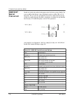
The relay provides overvoltage protection from both the bus and line PTs.
These functions are definite time delay functions.
Figure 4.15: 59 Main Overvoltage
The definite time delay main overvoltage function, similar to the undervoltage
function, looks at all 3 phase-to-neutral voltages. This function uses the RMS
voltages to make this determination of overvoltage and is settable to an AND
or OR logic.
The auxiliary overvoltage function operates exactly the same way as the main
overvoltage function except that it uses the voltages from the auxiliary PT in-
puts.
Table 4.11: 59 Overvoltage Settings
Main
Enable/Disable
Gate Switch
AND or OR
59 Va Main
59 Vb Main
59 Vc Main
T
0
Gate Switch (Setting)
Summary of Contents for L-PRO 4000
Page 1: ...L PRO 4000 Transmission Line Protection Relay User Manual Version 2 3 Rev 0...
Page 2: ......
Page 4: ......
Page 8: ......
Page 10: ......
Page 14: ......
Page 40: ......
Page 50: ......
Page 116: ......
Page 146: ......
Page 218: ......
Page 252: ...Appendix B IED Settings and Ranges Appendix B 34 L PRO 4000 User Manual D02706R02 30...
Page 260: ......
Page 270: ......
Page 302: ......
Page 308: ......
Page 310: ......
Page 312: ......


