4 Protection Functions and Specifications
D02706R02.30
L-PRO 4000 User Manual
4-33
60 CT
Supervision
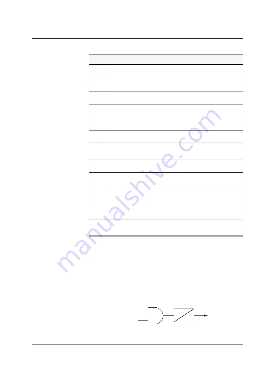
The relay provides CT secondary circuit supervision function for both main
and auxiliary CT’s. The element operates on presence of negative sequence
current Inps on main CT above the set vale and the absence of negative se-
quence voltage Vnps (below the set value, line PT) principle.
The auxiliary CT Supervision function operates exactly the same way as the
main CT Supervision function except that it uses the Inps current from the aux-
iliary CT in-puts.
Table 4.16: Logic Gates - Loss of Potential Logic
Logic
Gate #
Description (for details see Figure 4.17: Loss of Potential Logic on page 4-
31)
167
When 50Ipos or 503I0 exceed their set point and go HIGH (1) it will invert and
block logic element 169.
168
When one of the phase-to-ground potentials falls below 0.75 pu, the logic ele-
ment’s output is HIGH.
169
To declare a LOP, this element must have a negative rate of change of positive
sequence voltage below or less than 3 V/cycle - AND - an absolute value of rate
of change of positive sequence current below or less than 0.1 A/cycle - AND -not
have a positive sequence load current (50 Ipos) above the setting.- OR - not
have 3 times zero sequence fault current (3Io) above the setting of 3Io.
170
LOP is declared by this logic element (logic HIGH) when any of the phase cur-
rents are above 0.2 A.
171
Has an output when o/p from 168 is HIGH - AND - o/p from logic 173 is HIGH -
AND - “NOT” logic 176 HIGH. (Positive sequence rate of change voltage is not
greater than 3 V/cycle and not 3 phase voltage greater than 0.1 pu).
172
Has an output when o/p from 170 is HIGH - AND - positive sequence rate of
change voltage is not greater than 3 V/cycle.
173
Has an output when o/p from 171 is HIGH - OR - timed o/p from logic 169 is
HIGH.
174
Has a Loss of Potential (LOP) output when o/p from 168 is HIGH - AND - o/p
from logic 172 is HIGH - AND - o/p from logic 173 is HIGH. The output is timed on
drop out. This output is sent to other elements of the relay to give indication and
block voltage elements, such as impedance from tripping falsely from loss of
potential condition.
175
Phase voltage AØ and BØ and CØ less that 0.1pu will have output HIGH.
176
Logic element 175 HIGH and positive sequence rate of change voltage is not
greater than 3 V/cycle - output HIGH, will invert into element 171 to Block tuning
171 off.
Main CT Supervision Enabled
Main CT Inps > Pickup
Main PT Vnps < Pickup
T
O
Summary of Contents for L-PRO 4000
Page 1: ...L PRO 4000 Transmission Line Protection Relay User Manual Version 2 3 Rev 0...
Page 2: ......
Page 4: ......
Page 8: ......
Page 10: ......
Page 14: ......
Page 40: ......
Page 50: ......
Page 116: ......
Page 146: ......
Page 218: ......
Page 252: ...Appendix B IED Settings and Ranges Appendix B 34 L PRO 4000 User Manual D02706R02 30...
Page 260: ......
Page 270: ......
Page 302: ......
Page 308: ......
Page 310: ......
Page 312: ......


