4 Protection Functions and Specifications
D02706R02.30
L-PRO 4000 User Manual
4-45
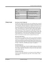
Group Logic
Group Logic Control Statements
The relay has 8 Setting Groups (SG). The user can change all relay setting pa-
rameters except the physical connections such as input or output parameters in
each setting group. Setting group changes are performed by using any one of
the 16 available Group Logic statements per setting group. The Group Logic
statements are similar to the ProLogic statements with the following excep-
tions – the sole function is to activate one of the 8 setting groups and the pro-
cessing is in a slower half second cycle. Group Logic inputs statements are
driven from ProLogic or any external input or virtual input or from previous
Group Logic statements. Each Group Logic statement includes 5 inputs (with
Boolean statements), one latch state and one pickup delay timer. The Active
Setting Group (ASG) is viewed from the Terminal Mode, the front panel or
from a record stored by the relay, the ASG is stored with the record).
Group Logic Processing
The 16 Group Logic statements reside in a slower processing thread within the
relay protection algorithms. The processing cycle happens once every half sec-
ond (0.5 second). When using ProLogic statements remember that a latch or
dropout timer should be used if the initiating condition does not last at least 0.5
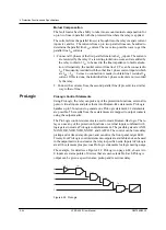
seconds. In the example following, we will create a definite pulse length using
ProLogic, for details see “L-PRO Setting Example” in Appendix L.
Default Setting Group
The relay uses Setting Group 1 as the factory default setting group and retains
the current active setting group in memory. This allows the relay to use the last
active setting group prior to interruption of relay power as the default setting
group following power up.
Change Active Group
The user can at any time change the active setting group. When initiating a set-
ting group change, this change takes precedence over an automatic setting
group change.
Table 4.26: ProLogic Setting Functions
Name
Give the ProLogic a meaningful name
Pickup Delay
Delay time from pickup to operate
Dropout Delay
Delay time from dropout to a ProLogic status
of low
A, B, C, D, E
Relay elements as input statements
Operators
Boolean-type logic gates
Summary of Contents for L-PRO 4000
Page 1: ...L PRO 4000 Transmission Line Protection Relay User Manual Version 2 3 Rev 0...
Page 2: ......
Page 4: ......
Page 8: ......
Page 10: ......
Page 14: ......
Page 40: ......
Page 50: ......
Page 116: ......
Page 146: ......
Page 218: ......
Page 252: ...Appendix B IED Settings and Ranges Appendix B 34 L PRO 4000 User Manual D02706R02 30...
Page 260: ......
Page 270: ......
Page 302: ......
Page 308: ......
Page 310: ......
Page 312: ......


