7
6
Installing the Ehubo – Standard
Electronic Control Module (ECM) Connection
NOTES
• If you are operating a pre‑2000 vehicle or post‑2000 vehicle with no ECM connection
(e.g. mechanical engine), refer to Installing the Ehubo – No ECM Connection.
• The engine must be turned off prior to installing Ehubo.
• Power supply must not be taken from any ABS/EBS braking system.
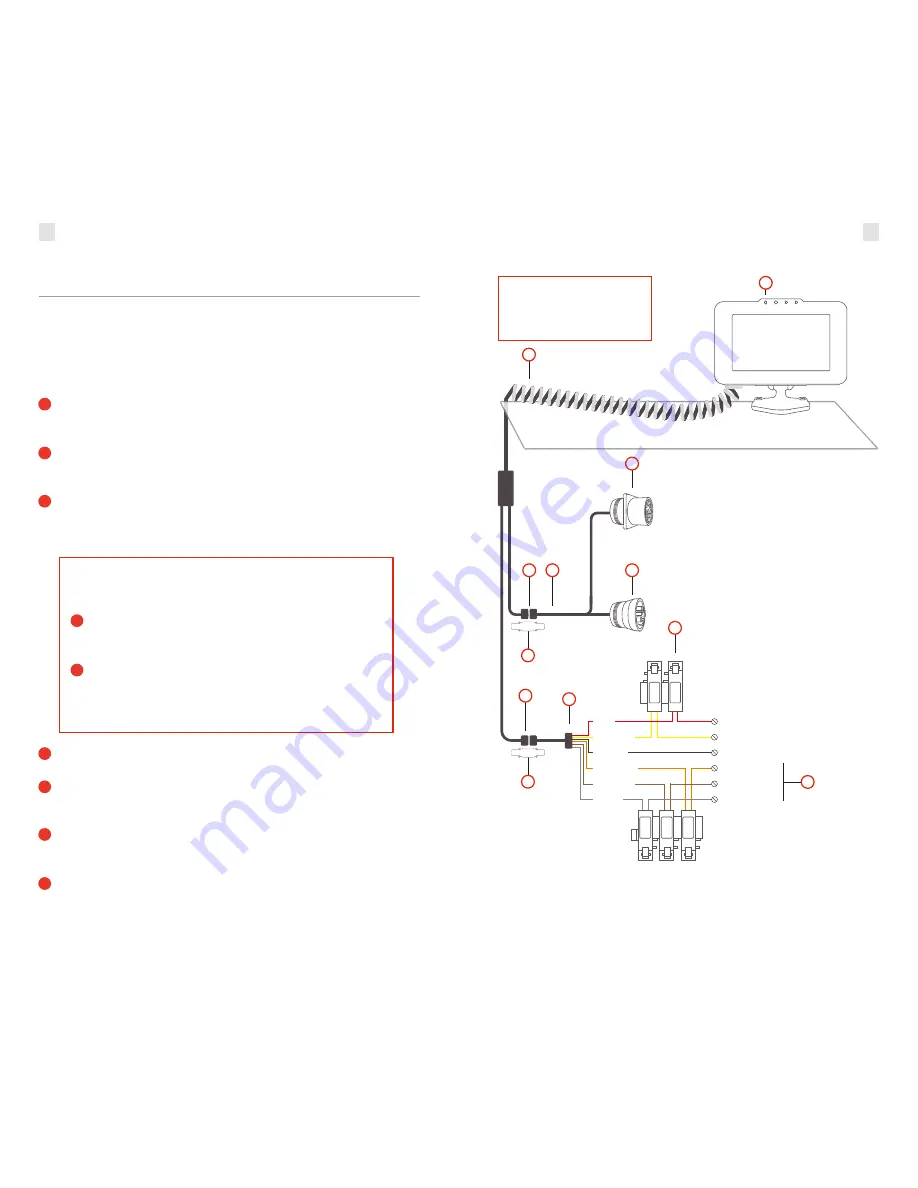
1.
Connect the 8‑way connector
(M)
on the extendable cable
(N)
to the corresponding
connector on the ECM Y cable
(O)
. Secure with the cable clamp
(J)
included in your
cable kit.
2.
Remove the vehicle’s diagnostic connector (data connector) from the bracket or panel
where it is fastened. Consult your vehicle’s maintenance guide to properly remove panels,
as required.
3.
Connect the vehicle’s diagnostic connector to the mating connector on the ECM Y
cable
(L2)
and secure by twisting the collar until it locks into place (tug lightly to check).
Your Ehubo display screen should power on at this point with a green LED
(P)
above
the display.
4.
Feed the second connector on the ECM Y cable
(L1)
into the existing vehicle diagnostic
connector housing and fasten to the vehicle.
5.
Optional. If additional wires (orange, brown and gray)
(R)
from the wiring harness
are required for monitoring activity through the three digital inputs, connect to their
respective sources with an inline 3A fuse.
6.
Store all unused wires neatly, insulated and secured using cable ties. Reinstall any
dashboard pieces or panels removed during installation. Remove the screen protection
film from the Ehubo display screen.
7.
Finalize by following the onscreen instructions. After the checks are successfully
completed, the Pending Assignment, or the Ehubo home screen (if unit is assigned to
a vehicle) is displayed. Ensure driver‑required manual and visor cards are in the vehicle.
IMPORTANT:
If Ehubo does not power on, connect the power through the Ehubo Wiring
Harness
(E)
:
1.
Connect the 10‑way connector
(Q)
on the Ehubo Extendable Cable
(N)
to the corresponding connector on the wiring harness
(E)
. Secure with
the cable clamp
(J)
included in the box.
2.
Connect the red wire from the wiring harness
(E)
to the inline fuse
(D)
,
and then to a permanent power source.
You must have constant 12‑24V power when the key is inserted with the
engine running, and when the key is not inserted with the engine off.
The Ehubo needs a permanent
power source and a good view
of the sky to operate optimally.
When the vehicle is off, the Ehubo shuts down to a lower power mode and draws a very small
current from the vehicle supply. Remove the Ehubo permanent power fuse if the vehicle is in
storage or parked up for more than a month to avoid discharging the vehicle battery.
1
1
2
2
3
4
5
6
7
O
M
Q
L2
J
J
D
R
E
L1
P
N
YELLOW
Switched
Power (Engine on/off)
Permanent
Power (12V or 24V)
Ground
Digital input 2
Digital input 3
BLACK
ORANGE
BROWN
GRAY
RED
Digital input 1
IG
N
+
ve
3A
3A
3A
EROAD
EROAD


