Pr
o
-
C
Series
12
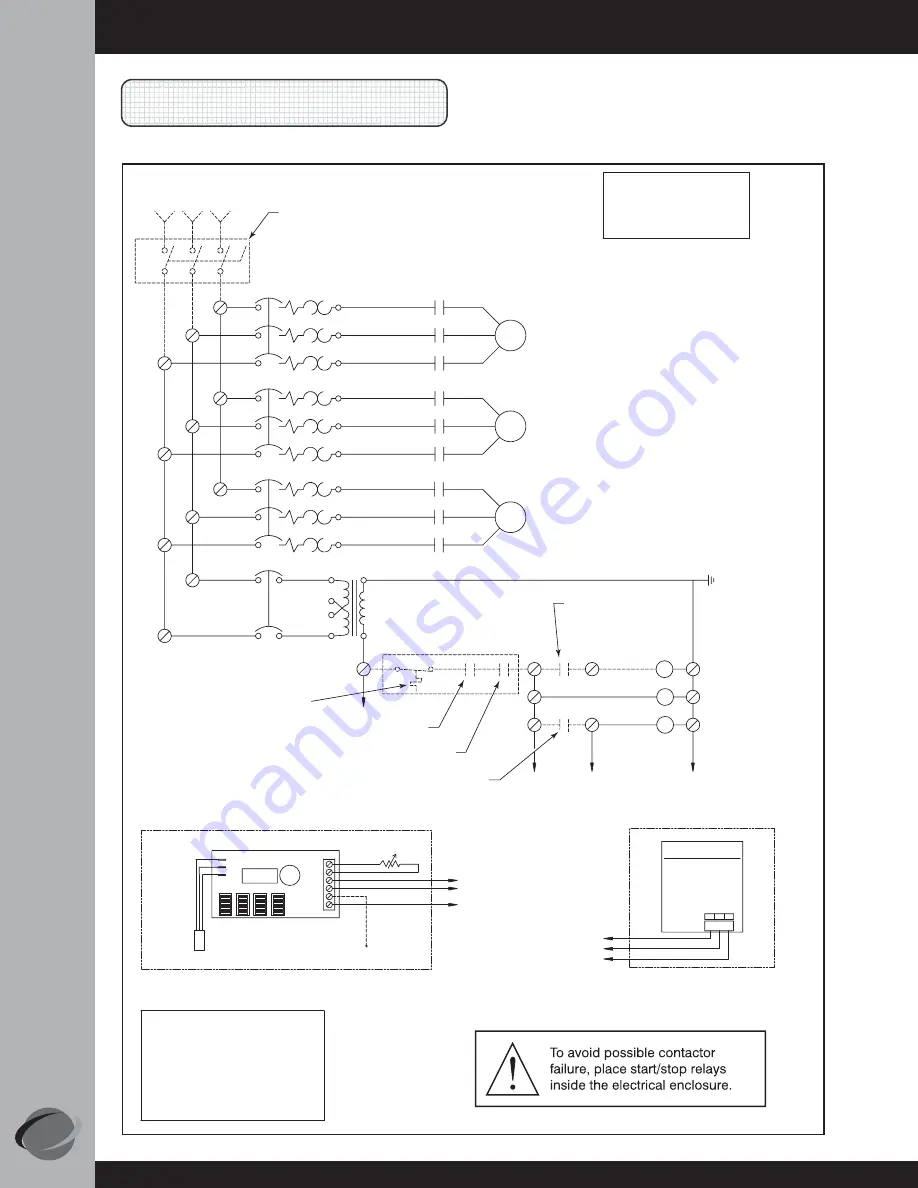
Outdoor Air Damper Actuator:
Belimo
Optional Stop/Jog Controller:
310-1875 Assembly (observe polarity)
Motion Detector Sensor
Optional
Model SMX70
Aux. Rotation Alarm (not used)
310-1865 Assembly
(See Note 3)
Thermistor Sensor
4
2
5
2
4
1
Line Power
480/240-208/3/60
H1
H1
H1
H2
H2
H3
Disconnect (by others)
*See Note 2
H3
H2
Exhaust Fan
Motor
Wheel
Motor
3CR
2CR
3CR
2CR
2CR
Supply Fan
Motor
1CR
1CR
1CR
USE COPPER
CONDUCTORS
ONLY
contactor (by others), 24VAC, 0.3 amps max.
at the preheater. (See specifications and circuit
diagram on electric preheater for information
4) If no options are ordered, terminals 1 & 2
are shipped with jumper installed.
2) If electric preheater is ordered, the power
any isolated contact, to prevent interconnection
1) All dashed lines indicate field wiring unless
to Preconditioner Panel and includes a disconnect
3) Alarm output: One triac-switch to drive a
5) Remote unit start/stop (by others) may be
wiring is factory installed from electric preheater
otherwise noted.
Notes:
electrical panel. Power wiring for the relay
be wired to the N.O. relay mounted on the
6) If Relay is ordered, terminals 1 & 2 will
of class 2 outputs, suitable for 24 VAC @ 3.5
amps.
on sizing and connecting supply power.)
coil is from the Carrier unit and is installed
by others.
H1
Supply Fan Remote Start/Stop
(by others, factory jumpered)
Optional Relay
*See Note 4,6
Optional Thermostat Frost Control
*See Note 4
Wheel Remote Start/Stop
(factory jumpered if optional
SMX70 controller not included)
Remote Unit Start/Stop (by others)
*See Note 4,5
1
2
1
2
2
2
4
5
5
3CR
3
2CR
1CR
4
4
4
H2
208/240/480 - 24VAC
75VA UL Cl 2 XFMR
H3
3CR
AWG Size
Tightening Torque
Slotted Screws
18-10
8
6-3
T1
GRN
WHEEL
ALARM
For
25
35
20
IN-LB
GRN
L1
RED
BLK
T2
BLK
COM
1
RED
+
2
WHT
+
3
BELIMO
M
M
M
3Ø Circuit Diagram, PRO-C-2400


