Pr
o
-
C
Series
4
Installation
Installation of the PRO-C unit is a relatively simple
procedure, but should be undertaken in a methodical fashion,
following the directions outlined in this manual.
The installation location should be chosen to provide
easy, convenient access. As with all mechanical equipment,
routine maintenance and inspection is necessary. Avoid
locations that are near or downwind of smoke, fumes or
exhaust outlets of other equipment. The front access panel
should have clearance space equal to the depth of the unit
to allow for service.
Once the installation location is determined, the PRO-
C should be un-skidded and closely examined for exterior
damage. Any defects or problems should be reported to
ERV Systems immediately.
After the exterior of the PRO-C is checked for obvious
damage, the front panel can be removed and the interior
checked. Inspect the interior of the unit for any damage.
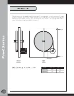
The ERV Systems energy recovery wheel is mounted
vertically inside the PRO-C unit. Verify that the wheel can be
spun by hand, clockwise from the left. The motor and belt
arrangement that turn the wheel are visible next to the wheel
at the access panel opening. The motor wires running to
the control panel are attached by a quick release disconnect.
The quick disconnect must be separated before sliding out
the wheel cassette. The wheel cassette need not be moved
for installation or hookup, but it can be pulled out for easy
maintenance and inspection purposes as instructed on page
19.
The unit identifi cation tag is located on the electrical
cabinet. It states the electrical requirements for the unit. The
main power connection to the unit should be made on the
control panel inside of the electrical cabinet (see the electrical
diagrams on pages 11-13). Make sure the power provided
to the installation site matches that required by the unit.
Note and verify that the voltage/phase/capacity needed and
provided are the same. Actual line voltage needs to be within
+/- 5% of the rated voltage for the unit to operate prop-
erly.
If the unit has been ordered with electric preheat, it
is shipped installed and the unit ID tag is located on the
heater. The main power connection to the unit is made at
the electric coil instead of the unit control panel (see the
electrical diagram on page 14).
Follow the linkup instructions provided on page 6.
Verify that the PRO-C is supported as instructed on page
5, if required.
After installation, attach the outdoor air hood and the
exhaust hood using the alignment holes on the unit. Note
that if the alignment holes are not used the unit may not
function properly. Units with an electric preheat require that
the outdoor air hood be centered on the heater opening.
Optional controls can be set and adjusted (see instructions
on pages 9 & 10). The outdoor and exhaust dampers can
be adjusted after the unit has been test run, as shown on
page 8.
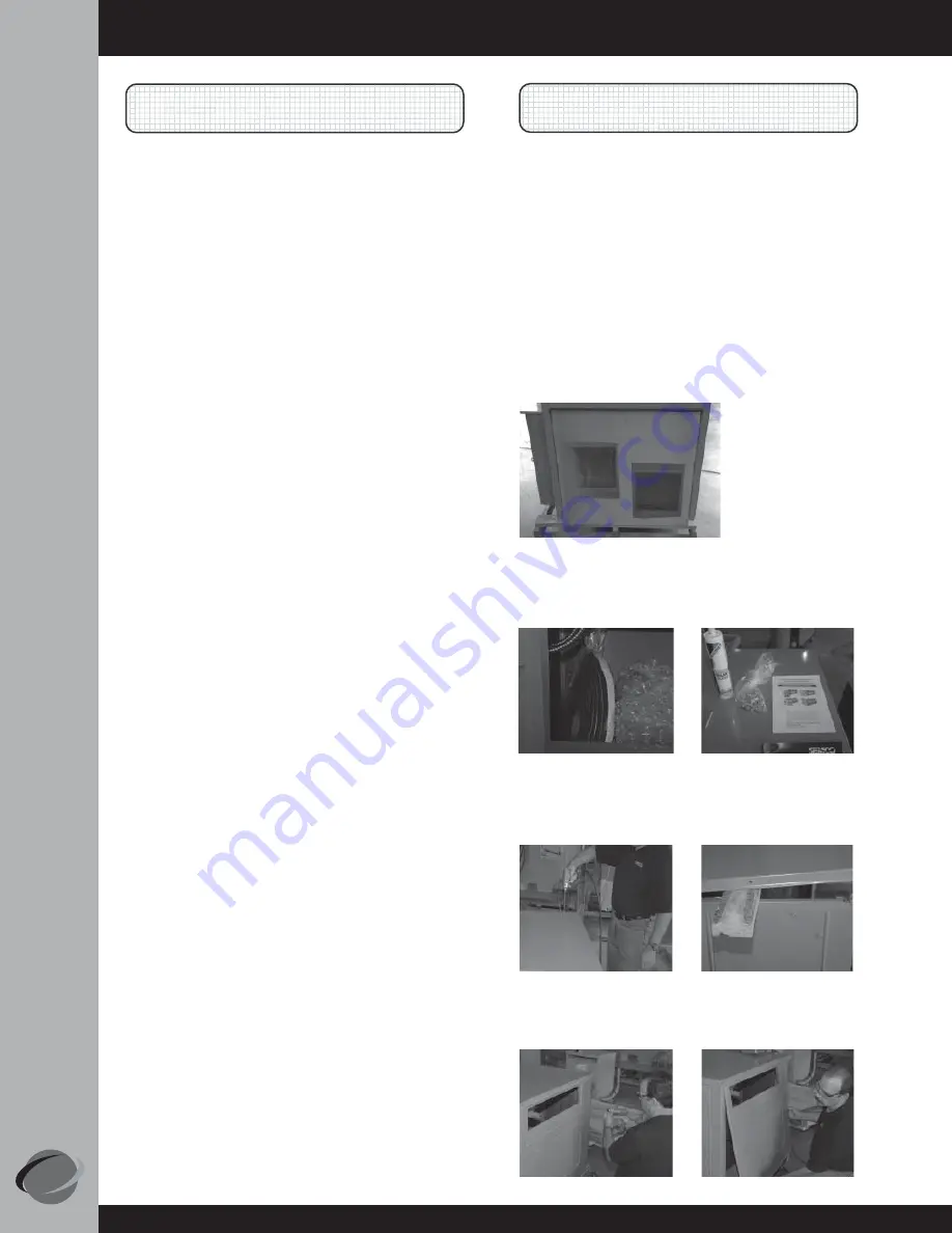
All materials required for installing the unit are provided:
Materials Supplied:
• Gasket
• PRO-C Support Angle
• Caulk
• Return Air Scoop
• #12 TEK screws • Supply Air & Exhaust Air Hoods
PRO-C-1000 Installation Instructions:
Linkup
1. Remove protective plastic from the Supply Air and
Return Air openings.
2. Within the Supply Air opening, remove all items
(manuals & parts).
3. Remove the screws from the roof of the Carrier unit,
lift, and block.
4. Remove the end panel of the Carrier unit.


