background image

Pr
o

-

C

 Series

5

5.  Install the PRO-C support angle to the base of  the 

carrier unit. (9 screws)

6.  Install the return air scoop to the return air opening of  

the PRO-C unit.

7.  Install the gasket to the left, right, and bottom facing 

edges of  the PRO-C unit.

8.  Bring the units together and set into place.

10. If  included, place the pedestal support at end of  the 

PRO-C unit, opposite the Carrier Unit.  The pedestal 
support is adjustable from 9” to 14”.

11. Caulk the left and right vertical seams on the Carrier 

unit as shown below.

12. Install the Outside Air and Exhaust Air hoods on the 

PRO-C unit.

9.  Lower the roof  of  the carrier unit so that it covers the 

top edge of  the PRO-C unit.  Install a minimum 3 #12 
Tek screws across the top fl ange of  the Carrier unit.

 3 Tek
screws

NOTE:  Rooftop unit fi lter access will be through the 
return air access panel (See Figure 5a.)

Summary of Contents for PRO-C-1000

Page 1: ...Installation Owners Manual PRO C Series Energy Recovery Ventilator For Carrier HJ TM and TF Rooftops Sizes 3 to 12 5 ton High Performance Ventilation Equipment PRO C 1000 PRO C 2400 ...

Page 2: ... of ERV Systems ERV Systems and the ERV System s logo are registered trademarks i PRO C Series 1 How it Works 1 Model Description 2 Definitions 2 Receiving Inspection 3 Overall Dimensions 3 Storage 3 Lifting Technique 3 Installation 4 Linkup 4 Support 7 Supply Exhaust Airflow Dampers 8 Controls 9 3Ø Circuit Diagram PRO C 1000 11 3Ø Circuit Diagram PRO C 2400 12 1Ø Circuit Diagram PRO C 1000 PRO C 24...

Page 3: ...uced size of the Carrier system Generally any first cost premium is paid back within the first year of operation Figure 1 An inside view of the PRO C ventilator with typical operating conditions during the cooling C and heating H season respectively How It Works The PRO C Series is a packaged system which includes supply and exhaust air fans outdoor and return air filter and a TEC total energy recove...

Page 4: ... cabinets motors fans and other parts that work together to make an effective energy recovery product Wheel Refers to the rotating wheel containing the coated media The stationary framework supporting the wheel is the wheel cassette 5 14 6 7 10 1 3 4 2 8 9 11 13 12 Adsorption The physical bonding of water vapor on the surface of the desiccant Cassette The framework supporting the wheel See also Wh...

Page 5: ...ings provided for ducting These openings make the internal equipment motors belts fans and insulation vulnerable to inclement weather conditions prior to installation and can cause standing water to accumulate inside the enclosure This is to be absolutely avoided H L W Table 1 Weights Dimensions Model L in H in W in Net Weight lbs PRO C 1000 47 86 30 19 31 38 350 PRO C 2400 54 75 38 81 40 38 475 T...

Page 6: ...s the electrical requirements for the unit The main power connection to the unit should be made on the control panel inside of the electrical cabinet see the electrical diagrams on pages 11 13 Make sure the power provided to the installation site matches that required by the unit Note and verify that the voltage phase capacity needed and provided are the same Actual line voltage needs to be within...

Page 7: ... pedestal support at end of the PRO C unit opposite the Carrier Unit The pedestal support is adjustable from 9 to 14 11 Caulk the left and right vertical seams on the Carrier unit as shown below 12 Install the Outside Air and Exhaust Air hoods on the PRO C unit 9 Lower the roof of the carrier unit so that it covers the top edge of the PRO C unit Install a minimum 3 12 Tek screws across the top flan...

Page 8: ... plastic from the Supply Air and Return Air openings 1 Open the fan door of the PRO C unit and remove all items manuals parts 5 Install the PRO C support angle to the base of the carrier unit 6 Install the right side angle trim to the Carrier unit and secure with screws 7 Install the bottom angle trim to the PRO C unit 8 Install the return air scoop to the return air opening of the PRO C unit ...

Page 9: ...Install the gasket to the left and right facing edges of the Carrier unit The PRO C unit is designed to support off the end of the Carrier unit A required optional pedestal support is avail able from ERV Systems for the PRO C series The PRO C series should not be installed without the pedestal support See Figure 5a This pedestal adjusts in height from 9 to 14 inches Support To install the pedestal...

Page 10: ...he damper to the set position when the remote unit start stop by others is off Note the actuator needs power to close therefore it is not recommended that the unit be turned off by disconnecting the power to the unit This may leave the actuator in an open position which may not be desirable To adjust the exhaust airflow damper turn the unit off and remove the nut bolt stops on both sides of exhaust...

Page 11: ...eezing point It is only necessary to keep the exhaust air temperature above the dew point This prevents condensation on the wheel so that all the moisture transfer occurs in the vapor phase The preheat control option includes a finned tube electric coil mounted on the outdoor air intake of the unit an SCR controller and a temperature sensor mounted in the outdoor air plenum The temperature for the ...

Page 12: ...arm when the SMX70 controller is in stop jog mode The alarm resets itself once the wheel begins to turn or the system is shut off and restarted Please note that the triac output for the alarm signal requires a load such as a contactor coil to operate This output may not register on a digital multimeter without the load or may cause a lamp with no limiting resistor to light dimly Thermostat Frost P...

Page 13: ... Panel and includes a All dashed lines indicate field wiring unless any isolated contact to prevent interconnection otherwise noted Notes 1 2 3 4 5 Electric Preheat If electric preheater is ordered of class 2 outputs suitable for 24 VAC 2 amps information on sizing and connecting supply power If Relay is ordered terminals 1 2 will be wired to the N O relay mounted on the electrical panel Power wir...

Page 14: ... Preconditioner Panel and includes a disconnect 3 Alarm output One triac switch to drive a 5 Remote unit start stop by others may be wiring is factory installed from electric preheater otherwise noted Notes electrical panel Power wiring for the relay be wired to the N O relay mounted on the 6 If Relay is ordered terminals 1 2 will of class 2 outputs suitable for 24 VAC 3 5 amps on sizing and conne...

Page 15: ...ISE NOTED F ELECTRIC PREHEATER IS ORDERED THE POWER WIRING IS FACTORY INSTALLED FROM ELECTRIC PREHEATER TO 0RECONDITIONER 0ANEL AND INCLUDES A DISCONNECT AT THE PREHEATER 3EE SPECIFICATIONS AND CIRCUIT DIAGRAM ON ELECTRIC PREHEATER FOR INFORMATION ON SIZING AND CONNECTING SUPPLY POWER LARM OUTPUT NE TRIAC SWITCH TO DRIVE A CONTACTOR BY OTHERS 6 AMPS MAX F NO OPTIONS ARE ORDERED TERMINALS ARE SHIPP...

Page 16: ...r 208 240V 1 60Hz electric heat coil 3Ø Electric Preheat Frost Control Circuit Diagram 1Ø Electric Preheat Frost Control Circuit Diagram F1 L1 H1 cutout airflow switch SC L2 L3 H3 F2 1 2 3 Solitech master controller SC SC fuse H1 H3 to main panel on SP unit remote duct stat with set point adjuster Line Power 208 240V 480V 3 60H delta or wye connected electric heat coils SC H2 manual cutoff H2 ...

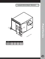
Page 17: ...o C S e r i e s 15 Segregated Exhaust Adapter Dimensions ACCESS OPENING AIR EXHAUST ISOMETRIC VIEW B D A C 2 32 TYPICAL UNIT SIZE A B C D PRO C 1000 10 83 10 83 2 52 10 83 PRO C 2400 14 76 14 76 3 23 14 76 ...

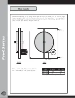
Page 18: ...o the wheel drive motor then remove the 2 tek screws located near the opening This will then allow you to pull the cassette out of the unit through the access door If the unit is equipped with a rotation sensor it must be removed prior to sliding the cassette out Remove links from the belt to tension The belt should deflect only 1 2 at the center of free area MODEL PRO C 1000 PROD C 2400 PRO C 1000...

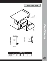
Page 19: ...W AIRFLOW AIRFLOW AIRFLOW PANEL ELECTRICAL PANEL Pro C Unit PREHEATER W D C H C B B A L PRECONDITIONER ELECTRICAL Model Dimensions inches W H L A B C D PRO C 1000 24 37 16 14 20 1 2 8 PRO C 2400 30 5 20 37 14 20 1 2 8 Electric Preheat Layout ...

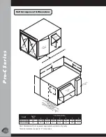
Page 20: ... C 2400 SERVICE CLEARANCE 24 OUTSIDE AIR ELECTRICAL PANEL C E F G Unit Arrangement Dimensions Model Net Wt lbs Dimensions inches A B C D E F G PRO C 1000 350 30 188 47 875 31 375 11 75 17 0 17 2 0 PRO C 2400 475 16 3 44 4 8 7 31 0 8 6 22 6 2 0 Note Dimensions F G represent approximate unit center of gravity Service clearance is equal to C dimensions ...

Page 21: ... that move through media flutes to keep them clean As the media moves constantly from one airstream to the other most dirt is blown away Some applications may require occasional rotor cleaning those receiving a great particle load for example Under these circumstances the media may be cleaned with a vacuum pressurized air or hot water However detergents or solvents are not recommended They may degr...

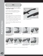
Page 22: ... installed belt length and will ensure optimum belt tension when running Note Every tenth link is designated with an arrow For multiple belt drives ensure that each belt has the same number of links Figure 15 Measuring the belt 1 Hold belt upside down Bend back as far as possible and hold with one hand Twist one tab 90 parallel with slot 2 Pull end of link over tab 3 Rotate belt end with tab 90 4 ...

Page 23: ... to add back one link to allow belts to be rolled on This does not apply if using Alternative Installation Method 1 Set motor to mid position of adjustment range and mark base clearly 2 Determine required belt length as in Measuring Belt Length 3 Push motor forward to minimum center distance 4 Install belts as in Installation 5 Pull motor back to previously marked mid position Like all high perfor...

Page 24: ...phone fax or e mail ERV Systems PO Box 1797 Columbia MO 65205 1797 Phone 573 886 5400 Fax 573 886 5401 sales ervsystems com www ervsystems com How to Reach Fenner Drives Fenner Drives 311 W Stiegel St Manheim PA 17545 1010 Phone 800 243 3374 Fax 717 665 2649 Contact Information ...

Page 25: ...OG 002 0807 1K G PO Box 1797 Columbia MO 65205 1797 573 886 5400 573 886 5401 fax www ervsystems com sales ervsystems com ...

Reviews: