background image

Cavi di collegamento / Connection cables / Câbles de raccordement / 
Schnittstellenkabel/ Cables de conexión 


IT


Per limitare al massimo l’influenza dei disturbi è necessario utilizzare cavi schermati di buona 
qualità. 
 
Caratteristiche del cavo di collegamento seriale: 
• 

Resistenza in corrente continua - Max. 151 Ohm/Km 

• 

Accoppiamento capacitivo - Max. 29pF/m 

• 

Schermatura > 80% oppure Totale 

In ogni caso: 
• 

Cercare il percorso più breve. 

• 

Effettuare la posa separata da cavi disturbati e/o cavi di potenza. 

• 

Utilizzare connettori con gusci metallici o di plastica conduttiva. 

 
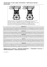
Collegare la schermatura del cavo seriale attenendosi alle indicazioni riportate nell’immagine 
seguente (FIG.1). 
 

NOTA

:  La  calza  deve  risultare  connessa  elettricamente  sia  al  corpo  connettore  che  al 

coperchio. 
Lo  schermo  del  cavo  deve  risultare  connesso  elettricamente  sia  alla  custodia  che  al  corpo 
del connettore stesso da ambo i lati del cavo. 
Nel  caso  che  non  possa  essere  eseguita  l'operazione  di  collegamento  schermo  lato 
Dispositivo causa tipo di connettore seriale particolare, la schermatura stessa dovrà essere 
portata esternamente al connettore e collegata al morsetto di terra. 
 

EN 

In  order  to  limit  as  much  as  possible  the  influence  of  these  disturbances  good  quality 
shielded cables must be used. 
 
Specifications of serial connection cable: 
• 

Direct current resistance - Max. 151 Ohm/Km 

• 

Capacity coupling - Max. 29pF/m  

• 

Shielding > 80% or total 

Always: 
• 

Find the shortest route. 

• 

Lay disturbed cables separately. 

• 

Use connectors with metal or conduc-tive plastic shells. 

 
Connect  the  serial  cable  shield  in  accordance  with  the  instructions  on  the  following  image 
(FIG.1). 
 

NOTE

: The braiding must be electrically connected both to the connector body and shell. 

The interface cable braiding must be electrically connected both to the shell and the body 
of the connector at both ends of the cable. 
If  the  connection  operation  cannot  be  carried  out  at  the  Device  side  due  to  the  particular 
type  of  serial  connector,  the  braiding  will  have  to  be  taken  outside  the  connector  and 
connected to the earth terminal. 
 

FR 

Pour  limiter  au  maximum  l’influence  de  ces  parasites  il  faut  utiliser  des  câbles  blindés  de 
bonne qualité 
 
Caractéristiques du câble de raccordement sériel :  
• 

Résistance en courant continu - Max. 151 Ohm/Km 

• 

Accouplement capacitif - Max. 29pF/m 

Summary of Contents for ERGO222A Series

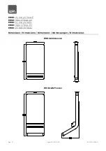
Page 1: ...te 20 02 2019 405 1300 254 0 ERGO PC INDUSTRIALE ERGO INDUSTRIAL PC ERGO PC INDUSTRIEL ERGO INDUSTRIAL PC ERGO PC INDUSTRIAL Dimensioni Dimensions Dimensions Abmessungen Dimensiones ERGO222Axxxxx ERGO222Txxxxx ...

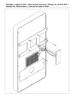
Page 2: ...Montaggio supporto VESA VESA support mounting Montage du support VESA Montage des VESA Ständers Montaje del soporte VESA ...

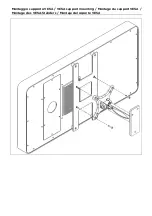
Page 3: ...Montaggio supporto VESA VESA support mounting Montage du support VESA Montage des VESA Ständers Montaje del soporte VESA ...

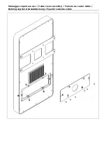
Page 4: ...Montaggio copertura cavi Cable cover assembly Fixation du cache câble Befestigung der Kabelabdeckung Fijación cubierta cable ...

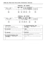
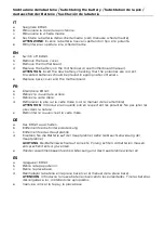
Page 5: ... DP DP DP DP DP port Porte DP DP Schnittstelle Puerto DP F USB USB USB USB A A A A Porta USB USB port Port USB USB Schnittstelle Puerto USB C 1 1 1 1 Port Port Port Porta a a a DP DP DP DP DP port Porte DP DP Schnittstelle Puerto DP G Porta Porta Porta Porta COM COM COM COM Porta seriale Serial port Port sériel Serielle Schnittstelle Puerto serie D 2 2 2 2 ETH10 100 1000 Mbit ETH10 100 1000 Mbit E...

Page 6: ...rez la couverture arrière c Retirez la carte mère d Remplacer la pile sur la carte mère voir le manuel de la carte mère ATTENTION Introduire la nouvelle pile en respectant les polarités Ne pas jeter les piles dans la nature e Remonter le couvercle et la carte mère DE a Das ERGO ausschalten b Entfernen Sie die hintere Abdeckung c Entfernen Sie das Hauptplatine d Ersetzen Sie die Batterie auf der Ha...

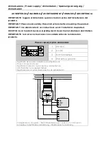
Page 7: ...se sorgfältig durch bevor Sie Installationen durchführen IMPORTANTE leer estas instrucciones con cuidado antes de la instalación producto Power supply 4 pins connectors 1 24 VDC 2 0 VDC 3 Not Connected 4 Protective ground Significato dei pin del connettore di alimentazione Power connector pin out Signification des pins du connecteur d alimentation Anschluß des Versorgungssteckers Significado de lo...

Page 8: ...ication ports could cause damage to certain components of the ERGO or of the devices connected to it IMPORTANT La masse des dispositifs connectés aux ports de communication parallèls ou sériels doit formellement être au même potentiel qu il 0V d alimentation du ERGO La circuòation d un courant entre il 0V d alimentation et la masse des ports de communication pouvait causer des dommages aux composa...

Page 9: ...hermatura stessa dovrà essere portata esternamente al connettore e collegata al morsetto di terra EN In order to limit as much as possible the influence of these disturbances good quality shielded cables must be used Specifications of serial connection cable Direct current resistance Max 151 Ohm Km Capacity coupling Max 29pF m Shielding 80 or total Always Find the shortest route Lay disturbed cabl...

Page 10: ...ungen für serielle Schnittstellenkabel Gleichstromwiderstand Max 151 Ohm Km Kapazitive Kopplung Max 29pF m Abschirmung 80 oder Komplettschirmung In jedem Fall Leitungen auf dem kürzesten Weg verlegen Datenleitungen getrennt von Lastleitungen verlegen Steckergehäuse aus Metall oder leitfähigem Kunststoff verwenden Schließen Sie die Abschirmung des seriellen Kabels gemäß den Anweisungen in der folge...

Page 11: ...est pas assurée dans les zones résidentielles Nutzungsbeschränkung Die Störfestigkeit für Wohnbereiche ist nicht gegeben Restricción de uso los requisitos de protección no esté garantizado en zonas residenciales Porte di comunicazione Communication ports Portes de comunication Schnittstellen Anschlüsse Puertos de comunicación Per il collegamento ai connettori delle periferiche fare riferimento all...

Page 12: ...ty EN 61000 6 2 2005 and thus are in line with Council Directive EMC 2004 108 EC Tous les produits décrits dans ce manuel sont conformes aux standards suivants compatibilité electromagnétique EMC émissions EN 61000 6 4 2007 immunité EN 61000 6 2 2005 et ils répondent pour cela aux Council Directive EMC 2004 108 EC Alle im vorliegenden Handbuch beschriebenen Produkte sind konform mit den folgenden ...

Reviews: