10
SECTION 2 INSTALLATION
TABLE 2.1 Recommended Input Fuse Size
Full
Primary
Load
Input
Line
Fuse
Volts
Amperes
Size
208
52
90
230
58
90
380
36
50
400
34
50
415
32
50
460
31
40
575
25
30
2.2.2 INPUT CONDUCTOR CONNECTIONS
The unit is provided with a three conductor primary input
cable without plug. The ground lead (green) of this cable
should be connected to a reliable ground and the two
remaining wires (black and white) should be connected
to the separately fused lines of the disconnect or breaker.
See Table 2.1 for recommended fuse sizes to use in the
disconnect.
All units leave the factory with their primary electrical
input requirements internally-connected for the highest
voltage rating available (e.g.: 460-volt for the 200/230/
460-volt units; and 575-volt for the 230/460/575-volt
units).
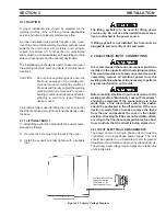
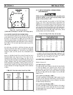
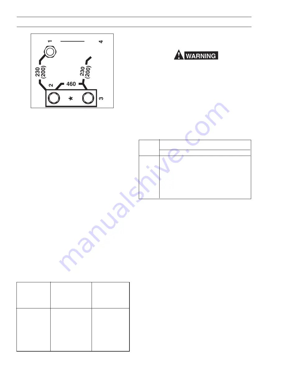
Remove right side panel from unit and locate the input
terminal board (see Figure 2.2). If the unit is to be
operated from another input voltage, the links on the
input terminal board must be reset for that particular input
voltage. Always verify the input voltage and check the
link arrangement regardless of factory setting. The volt-
age links are setup by reconfiguring the copper link bars
to the silkscreened voltage designation for the desired
voltage.
2.3 OUTPUT WELDING CONNECTIONS
(SECONDARY)
Before making any connections to the power source
output terminals, make sure that all primary input
power to the machine is off.
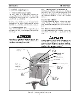
The output terminals are located on the front panel
(Figure 2-3). Two output terminals are provided. The
NEGATIVE (-) terminal is located on the left side and the
POSITIVE (+) terminal is located on the right side. The
output cable connections will depend on the materials to
be welded and on the welding process desired. Table 2-
2 provides the recommended cable output sizes. Keep
welding cables as short as possible.
Table 2-2. Output Cable Sizes (Secondary)
Welding
Total Length (Feet) of
Current
Cable in Weld Circuit*
50
100
150
200
250
100
6
4
3
2
1/0
150
4
3
1
1/0
2/0
200
3
1
1/0
2/0
3/0
250
2
1/0
2/0
3/0
4/0
300
1
2/0
3/0
4/0
4/0
400
2/0
3/0
4/0
4/0
2-2/0
500
3/0
3/0
4/0
2-2/0
2-3/0
* Total cable length includes work and electrode cables. Cable size
is based on direct current, insulated copper conductors, 100-
percent duty cycle and a voltage drop of 4 or less volts. The welding
cable insulator must have a voltage rating that is high enough to
withstand the open circuit voltage of the machine.
2.4 CONTROL CONNECTIONS
Refer to Figure 2-3.
2.4.1 Wire Feeder Control
The Wire feeder control cable connection is provided by
a 19-pin receptacle (J1) located at the center of the
power source front panel. This receptacle will operate
ESAB wire feeders with 19 pin control cables including
the Mig 2E, Mig 4HD, Mobile Master 2cv and Mobile
Master 2cvcc.
2.4.2 - 42V Circuit Breaker (CB2)
The 42V resettable circuit breaker (CB2) located on the
power source front panel protects the 42 volt wire feeder/
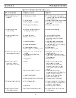
control circuitry against over current. (Table 5-1 provides
troubleshooting information).
2.4.3 - 24V Circuit Breaker (CB1)
The 24V resettable circuit breaker located on the power
source front panel (CB1) protects the 24 volt control
circuitry against over current. (Table 5-1 provides trouble-
shooting information.
DANGER
HIGH
VOLTAGE
Figure 2.2 - Input Terminal Board
(208/230/460V Illustrated in the 460 Volt Configuration)
* Double Links


