background image

SECTION  5                                                                       TROUBLESHOOTING

17

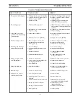
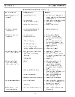
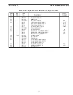
TABLE 5.1 TROUBLESHOOTING GUIDE

WELD CONDITION

POSSIBLE CAUSE

REMEDY

1. No weld or control power.

a. Primary input power not available.

a. Check for Voltage at primary input.

b. Faulty connection, primary input

b. Repair or replace cable or switch

cable, or power switch

as necessary.

c. Blown line fuse.

c. Replace fuse. If it blows again,

contact ESAB representative.

2. No welding power.

a. Thermostat has opened.

a. Wait 15 minutes with fan running. If

still no power, contact ESAB repre-

sentative.

b. Shorted S.C.R. in main rectifier.

b. Check S.C.R. and replace if req’d.

c. Open in wiring

c. Check all wiring.

3. Fan does not run. No

a. See Weld Condition 1.

a.  Repair or replace cable or switch

problem - thermostatically

as necessary.

controlled fan.

b. Defective fan motor (MTR1)

b. Replace fan motor (MTR1).

4. Erratic welding current.

a. Poor workpiece connection.

a. Check workpiece connection.

b. Loose welding connections.

b. Check all connections.

c. Wrong polarity.

c. Check for correct polarity.

5. Welding output Voltage

a. Low line Voltage.

a. Use correct voltage.

and/or current too low.

b. Welding cables too long or too

b. Use correct cable size.

small.

c. Loose connection.

c. Check all welding cable

connections.

d. Defective capacitor bank.

d. Check capacitors for low

leakage resistance.

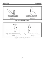
6. Stringy irregular bead,

a. Torch moved too fast.

a. Move torch slower along seams.

poor penetration.

b. Controls are not set properly for

b. Reset control properly.

metal gauge thickness.

c. Wrong polarity.

c. Check for correct polarity.

7. Bead not centered.

a. Nozzle not aligned.

a. Move torch nozzle parallel to

and centered over seam.

8. Bead too large.

a. Torch moved too slowly.

a. Move torch faster along seam.

9. Unstable arc, excess

a. Incorrectly set controls.

a. Reset controls.

spatter, weld porous.

b. Shield gas flow is too low or

b. See Condition 10.

stopped.

c. Torch nozzle is too far from work.

c. Maintain 1/4" (6 mm) wire

tip to work; hold closer to work.

d. Faulty regulator or adapter.

d. Check flow at outlet;

replace faulty item.

e. Faulty gas solenoid valve.

e. Replace solenoid valve.

f. Wrong polarity.

f. Check polarity.

Summary of Contents for 251cv

Page 1: ...is equipment Do NOT attempt to install or operate this equipment until you have read and fully understand these Instructions If you do not fully understand these Instructions contact your supplier for further information Be sure this information reaches the operator You can get extra copies through your supplier This manual provides complete instructions for the following packages starting with Se...

Page 2: ...wer Source 7 1 3 2 Optional Controls 7 1 4 Optional Accessories 7 1 4 1 MT 250SG Spool on Gun 7 1 4 2 ST 23A Spool On Gun Torch and Adaptor Kit 7 1 4 3 TR 24 and TR 251cv Trucks 7 1 4 4 Torch Wire Feed Accessories 7 1 5 Safety 7 1 6 Duty Cycle and Curves 7 1 7 Volt Ampere Curves 8 SECTION 2 INSTALLATION 9 2 1 Location 9 2 1 1 Lifting Eyebolt 9 2 2 Electrical Input Connections 9 2 2 1 Input Electri...

Page 3: ...es on the workpiece which might pro duce flammable or toxic vapors Do not do hot work on closed containers They may explode 4 Have fire extinguishing equipment handy for instant use such as a garden hose water pail sand bucket or portable fire extinguisher Be sure you are trained in its use SAFETY PRECAUTIONS 11 95 5 Do not use equipment beyond its ratings For example overloaded welding cable can ...

Page 4: ... Compressed Gas Association 1235 Jefferson Davis Highway Arlington VA 22202 EQUIPMENT MAINTENANCE Faulty or im properly maintained equipment can cause injury or death Therefore 1 Always have qualified personnel perform the installa tion troubleshooting and maintenance work Do not perform any electrical work unless you are qualified to perform such work 2 Before performing any maintenance work insi...

Page 5: ...oigné de la zone de travail augmente en effet le risque de pas sage d un courant de sortie par des chaînes delevage PRÉCAUTIONS DE SÉCURITÉ AVERTISSEMENT Ces règles de sécurité ont pour objet d assurer votre protection Veillez à lire et à observer les précautions énoncées ci dessous avant de monter l équipement ou de commercer à l utiliser Tout défaut d observation de ces précautions risque d entr...

Page 6: ...ticulières en matière de ventilation indiquées à l alinéa 6 de la norme Z49 1 de l AWS 5 ENTRETIEN DE L ÉQUIPEMENT Un équipement entretenu de façon défectueuse ou inadéquate risque non seulement de réaliser un travail de mauvaise qualité mais chose plus grave encore d entraîner des dommages corporels graves voire mortels en déclenchant des incendies ou des chocs électriques Observez par conséquent...

Page 7: ...ry 10 This cycle can be repeated indefinitely See Figure 1 1 1 1 GENERAL This manual has been prepared especially for use in familiarizing personnel with the design installation op eration maintenance and troubleshooting of this equip ment All information presented here in should be given careful consideration to assure optimum performance of this equipment 1 2 RECEIVING HANDLING Prior to installi...

Page 8: ...ight 20 9 inches 530 mm Width 12 9 inches 330 mm Depth 26 1 inches 660 mm Fig 1 1 Duty Cycle Curves Figure 1 2 Volt Ampere Curves DUTY CYCLE WELDING AMPERES 20 25 30 35 40 50 60 70 80 90 100 300 250 200 150 RATED OUTPUT VOLTS AMPS 1 7 VOLT AMPERE CURVES Figure 1 2 The Volt Ampere curves show the output voltage avail able at any given output current for the various Voltage Selector positions The ac...

Page 9: ...nt of performance due to an overloaded circuit The primary input voltage requirements are noted on the unit s rating plate 2 1 LOCATION A proper installation site should be selected for the welding machine if the unit is to provide dependable service and remain relatively maintenance free A proper installation site permits freedom of air move ment into and out of the welding machine and also least...

Page 10: ...eft side and the POSITIVE terminal is located on the right side The output cable connections will depend on the materials to be welded and on the welding process desired Table 2 2 provides the recommended cable output sizes Keep welding cables as short as possible Table 2 2 Output Cable Sizes Secondary Welding Total Length Feet of Current Cable in Weld Circuit 50 100 150 200 250 100 6 4 3 2 1 0 15...

Page 11: ...ition output voltage is controlled by adjusting the voltage control knob on the front panel to the desired output In the Remote posi tion output is controlled at the wire feeder or remote control 3 1 4 VOLTAGE CONTROL This control allows the operator to adjust the output voltage Placing the Panel Remote switch in the Re mote position disables the voltage control on the front panel 3 1 5 FEEDER SEL...

Page 12: ...reathing air DO NOT bring gas cylinders into confined spaces When leaving a confined space shut OFF gas supply at the source to prevent gas from leaking into thespace iftheswitchisaccidentlykeptdepressed Check the breathing atmosphere in the confined space to be sure it is safe to reenter E Never operate the equipment at currents greater than the rated ampere capacity Overheating will occur F Neve...

Page 13: ...stat in the transformer windings which will open and prevent the contactor from closing if the transformer windings are overheated If the thermostat opens the ready light will go out Allow the equipment to idle with fan running until the light comes back on before attempting to weld again b Attempting to weld over grease or oil can cause weld defects c Before welding on aluminum be sure to clean s...

Page 14: ...SECTION 3 OPERATION 14 Figure 3 2 Continuous Weld Conditions Figure 3 3 Angle of Welding Wire with Joint FILLET WELD BUTT WELD 45 90 10 10 TRAVEL TRAVEL ...

Page 15: ...y by blowing it out with compressed air This cleaning operation is necessary so that maximum cooling will be accomplished by the air stream This should be done periodically depending upon the location of the unit and the amount of dust and dirt in the atmosphere The hermetically sealed silicon rectifiers are specially designed for welding machine use and will not age or deteriorate in use The diod...

Page 16: ...s B Isolate trouble to one part of the welding installation primarypowersupply powersource Feederorwire guidetrain casing driverolls linersandcontacttip If this inspection indicates trouble in the Feeder use Troubleshooting Guide in the feeder manual Many troubleshooting situations require that the power remain On and that power terminals in the equipment carry voltage Exercise extreme caution whe...

Page 17: ...ctions c Wrong polarity c Check for correct polarity 5 Welding output Voltage a Low line Voltage a Use correct voltage and or current too low b Welding cables too long or too b Use correct cable size small c Loose connection c Check all welding cable connections d Defective capacitor bank d Check capacitors for low leakage resistance 6 Stringy irregular bead a Torch moved too fast a Move torch slo...

Page 18: ...lls or replace 13 Wire does not feed motor a Kink etc in wire or wire bound a Straighten or feed wire until running drive roll turns on reel clear and cut off b Wire freezing to contact tip b Free freeze or remove contact burnback tip feed wire until clear cut end free and replace tip c Clogged liner c Replace liner 14 Wire does not feed a Motor a With wire speed dial on 700 motor NOT running pres...

Page 19: ...19 D 37309 B Figure 5 1 Schematic Diagram 251cv Power Source All Models ...

Page 20: ...20 D 37310 B Figure 5 2 Wiring Diagram 251cv Power Source All Models ...

Page 21: ... warranty Replacement parts may be ordered from your ESAB distributor or from ESAB Welding Cutting Products Attn Customer Service Dept PO Box 100545 Ebenezer Road Florence SC 29501 0545 Be sure to indicate any special shipping instructions when ordering replacement parts To order parts by phone contact ESAB at 1 843 664 5540 Orders may also be faxed to 1 800 634 7548 Be sure to indicate any specia...

Page 22: ...22 SECTION 6 REPLACEMENT PARTS Figure 6 1 251cv Power Source Front View 2 1 16 4 3 17 5 6 7 8 9 10 11 19 18 12 13 3 14 15 20 Male Plug not shown 21 Eye Bolt not shown ...

Page 23: ...d 10 1 13730632 Potentiometer 10K 2W R1 11 1 37306YL Cover Top 12 1 34141GY Cover Option optional Meter Kit shown 13 1 952206 Light Indicator 28V White PL1 14 2 2062161 Circuit Breaker 5A CB1 2 15 1 36107 Switch Power 600V 63A with knob S3 16 1 954008 Label Danger High Voltage 17 2 13734588 Logo ESAB Clear 18 1 2091514 Label Warning 19 1 954747 Label Schematic Inside Top Cover 20 2 13733936 Quick ...

Page 24: ...24 SECTION 6 REPLACEMENT PARTS 33 32 41 42 35 36 37 39 38 34 31 Figure 6 2 251cv Power Source Right Side View 40 43 44 45 ...

Page 25: ...3730583 Term Bushing 687 37 1 952683 Fuse Solid State F2 38 1 32261 Board Term Input 200 230 460 V TB1 1 32265 Board Term Input 230 460 575 V TB1 1 32266 Board Term Input 220 400 V TB1 39 2 or 3 672065 Strap Terminal 40 1 36800GY Fan Bracket 41 1 37304GY Rear Panel 42 1 954743 Label Rating 200 230 460 V 1 954744 Label Rating 230 460 575 V 1 954745 Label Rating 220 400 V 43 1 950711 Switch Thermal ...

Page 26: ...26 SECTION 6 REPLACEMENT PARTS 52 54 53 63 62 55 56 57 58 59 64 Figure 6 3 251cv Power Source Left Side View 51 65 60 61 Bottom of 58 ...

Page 27: ... Pos TB2 56 1 950760 Relay Enclosed DPDT 24V 10A K1 57 1 23604891 Label High Voltage Warning 58 1 952566 Heatsink SCR 59 2 952564 SCR 180A SCR1 2 60 1 950710 Switch Thermal 130 F not shown front TS4 61 1 950711 Switch Thermal 194 F not shown rear TS1 62 1 36806 Bus Cap Pos 63 1 17250200 Resistor 20 Ohm 50W R3 64 1 36810 Cable Power Input 65 1 97W63 Connector Cable Grip Parts List for Figure 6 3 25...

Page 28: ...air Stations C TECHNICAL SERVICE Telephone 800 ESAB 123 Fax 843 664 4452 Part Numbers Technical Applications Hours 8 00 AM to 5 00 PM EST Performance Features Technical Specifications Equipment Recommendations D LITERATURE REQUESTS Telephone 843 664 5501 Fax 843 664 5548 Hours 7 30 AM to 4 00 PM EST E WELDING EQUIPMENT REPAIRS Telephone 843 664 4469 Fax 843 664 5557 Repair Estimates Repair Status ...

Reviews: