23
SECTION 5
MAINTENANCE
SECTION 6
REPLACEMENT PARTS
6.1 GENERAL
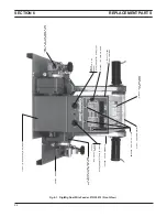
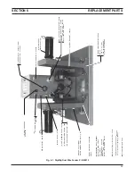
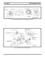
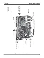
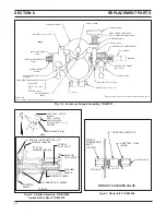
Replacement Parts are illustrated on the following fig-
ures. When ordering replacements parts, order by part
number and part name, as illustrated on the figure. DO
NOT ORDER BY PART NUMBER ALONE.
Always provide the series or serial number of the unit on
which the parts will be used. The serial number is
stamped on the unit nameplate.
6.2 ORDERING
To assure proper operation, it is recommended that only
genuine ESAB parts and products be used with this
equipment. The use of non-ESAB parts may void your
warranty.
Replacement parts may be ordered from your ESAB
distributor or from:
ESAB Welding & Cutting Products
Attn: Customer Service Dept.
PO Box 100545, Ebenezer Road
Florence, SC, 29501-0545
Be sure to indicate any special shipping instructions
when ordering replacement parts.
To order parts by phone, contact ESAB at 1-803-664-
5540 or 4460. Orders may also be faxed to 1-800-634-
6548. Be sure to indicate any special shipping instruc-
tions when ordering replacement parts.
Refer to the Communication Guide located on the last
page of this manual for a list of customer service phone
numbers.
5.1 GENERAL
If this equipment does not operate properly, stop
work immediately and investigate the cause of the
malfunction. Maintenance work must be performed
by an experienced person, and electrical work by a
trained electrician. Do not permit untrained persons
to inspect, clean, or repair this equipment. Use only
recommended replacement parts.
5.2 INSPECTION AND CLEANING
A. GENERAL MAINTENANCE
Little maintenance is required to keep the wire feeder in
top operating condition. It is important, however, that
moving parts such as feed and pressure rolls, wire feed
motor, etc., be kept clean and free of dust or dirt.
Cleaning is best accomplished by regularly blowing off
these parts with dry compressed air. This should be
done once for every eight hours of operating time, more
often if necessary.
B. LUBRICATION OF DIGITAL MOTOR-GEAR UNIT
The EH-10A motor-gear digital unit is lubricated with a
heavy duty grease when assembled at the factory and
should not require further lubrication unless disas-
sembled. If disassembled relubricate with Texaco
Multifak grease.
C. CHECK OR REPLACEMENT OF MOTOR BRUSHES
Motor brushes should be checked periodically. If a
brush is broken, or worn down to less than 3/8-in. length,
it must be replaced. Brushes can be inspected by
unscrewing the brush-holder plug and withdrawing the
brush assembly. Never remove a brush without
matchmarking it and its holder, so that it can be replaced
in the same holder in its original position.
D. REMOVAL OF EH-10A DIGITAL WELDING HEAD
1. Unplug the control cable from the rear panel of the
wirefeeder control.
2. Remove the accessory support assembly from the
motor-gear unit by loosening the cap screw at the
bottom of the assembly.
3. Disconnect the motor and tachometer cables from
terminal board (T1) inside the control assembly as
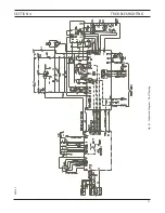
shown on the wiring diagram.
4. Remove the four screws which secure the digital
motor-gear unit to the base and remove the digital
unit.
E. ADDITIONAL DIGIMIG PROGRAM FEATURES
The Digimig’s MPU board contains an integral 4-rocker
“dip” switch (SW1) that is factory-set to the following
positions: Rocker #1, #2, 3, 4 are all OPEN. The
microprocessor technology utilized by the Digimig con-
trol is extremely versatile and can be modified for
specific purpose by ESAB’s engineering services group.
To add specific features or programs to your unit,
consult your ESAB representative. If additional optional
features are provided, the SW1 rocker positions may
need to be repositioned — and this information will be
conveyed in the appropriate instruction booklets pro-
vided with the option kits.
Summary of Contents for Digimig Dual
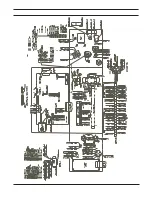
Page 21: ...21 SECTION 4 TROUBLESHOOTING Fig 4 1 Schematic Diagram Dual Digimig 30914 L ...
Page 22: ......
Page 29: ...29 NOTES ...
Page 30: ...30 NOTES ...


