5
SECTION 1
DESCRIPTION
1.1 GENERAL
This Digimig wire feeder is designed as a “dual” torch
welder with each torch capable of furnishing two com-
pletely different sets of welding parameters—in other
words, four (4) completely different welding schedules
can be preset to meet the requirements of high production
shops. The standard Dual control features include power
source, slope, wire type, wire diameter selections, and
presettable wire feed speed (ipm), voltage, pre and
postflow gas shielding, cold wire inching, gas purging,
adaptive or manual burnback and spot welding time
functions.
The Digimig Dual torch welder is a microprocessor
controlled digital wire feeder designed for mig short arc
and spray arc, and flux core welding applications. Its
electronic brain (the microprocessor) not only controls, it
also remembers and automatically coordinates the pro-
gram sequencing (that “you” preset) which results in the
most accurate wire feed speed and voltage control
possible.
By virtue of its microprocessor controlled wire speed and
arc voltage design, the Digimig Dual allows the customer
to preset both welding parameters (for each torch), lock-
them-in, and be assured that each setting will be precisely
held regardless of changes in line voltage, arc or load
conditions.
Two digital readout windows continuously display (1/2-in.
high) the preset welding parameters (speed and voltage).
After the arc is struck, they automatically display the
actual wire speed and arc voltage conditions for the
selected schedule. The read-outs can also provide select-
able displays of power source and slope, and wire type
and diameter used, and other welding parameters such as
inching speed, gas pre- and postflow times, spot time in
seconds and manual burnback time in cycles.
The Dual Digimig uses a pair of heavy duty EH-10A wire
drive motors designed to feed hard or soft wires from .030-
in. to 1/16-in. in diameter and flux-cored wires from .035-
in to 5/64-in. in diameter. Rate of wire feed (20-999 ipm)
is precisely controlled by using a closed-loop “J” governor
digital feedback circuit that employs an optical tachometer
to monitor the motor speed. Arc voltage regulation is also
controlled by a closed-loop digital feedback circuit that
monitors the arc voltage and automatically adjusts the
power source output voltage to maintain the preset voltage.
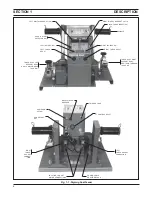
For identification and location of all functional controls and
connections refer to Figure 1-1. The front panel contains
the torch switch receptacles which use low voltage, d.c.,
for operator safety. The rear panel contains the on-off
power switch, the run/set switch, trigger lock switch, a 7-
ampere reset circuit breaker for overload protection, a 19-
pin receptacle (J1) provides 115vac and contactor con-
trol, arc monitoring and control signals from the power
source.
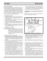
All interconnecting cable, hose and auxiliary equipment
connections are quickly detachable to provide easy setup
and maximum portability of the wire feeder as shown in
Figs. 2-1 & 2-2. A water kit may be purchased, as an
optional accessory, for use with water-cooled torch
operation.
1.2 SCOPE
The purpose of this manual is to provide the operator with
all information required to install and operate the Dual
Digimig wire feeder. Technical information and reference
material is also provided to assist in troubleshooting.
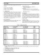
1.3 SPECIFICATIONS
Input Power Required ......................... 115 volts 50/60 Hz single phase
Feed Speed Range .............................. 20-999 in./min. (.5-26.4 m/min.)
Wire Sizes Accommodated:
Hard/Soft — ......................................... .030 thru 1/16-in. (.8 thru 1.6 mm)
Flux Cored — .................................. .035 thru 5/64-in. (0.9 thru 2.0 mm)
Length ............................................................................. 24-in. (610 mm)
Width ......................................................................... 22-1/2-in. (572 mm)
Height .............................................................................. 15-in. (381 mm)
Weight (less wire) ............................................................. 80-lbs. (36 kg)
1.4 REQUIRED EQUIPMENT
A. CONSTANT VOLTAGE POWER SOURCE
One of the following power sources must be used:
SVI-300i cv/cc, P/N 34835.
VI-450, P/N 33322.
SVI-450i, P/N 31950
V-650 cv/cc, P/N 33324.
B. Cable Assemblies
115 Volt/Contactor/Remote Control J1 Cable, 19-con-
Summary of Contents for Digimig Dual
Page 21: ...21 SECTION 4 TROUBLESHOOTING Fig 4 1 Schematic Diagram Dual Digimig 30914 L ...
Page 22: ......
Page 29: ...29 NOTES ...
Page 30: ...30 NOTES ...


