background image

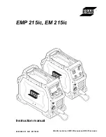
Instruction manual

0463 408 001 GB 20170228

Valid for: serial no. EMP: 615-xxx-xxxx, EM: 627-xxx-xxxx

EMP 215ic, EM 215ic

Summary of Contents for EM 215ic

Page 1: ...Instruction manual 0463 408 001 GB 20170228 Valid for serial no EMP 615 xxx xxxx EM 627 xxx xxxx EMP 215ic EM 215ic...

Page 2: ......

Page 3: ...wire feed pressure 20 5 6 Changing the feed pressure rollers 20 5 7 Shielding gas 21 5 8 Duty cycle 22 5 9 Overheating protection 23 6 CONTROL PANEL 24 6 1 How to navigate EMP 215ic 24 6 1 1 Main menu...

Page 4: ...TABLE OF CONTENTS 0463 408 001 ESAB AB 2017 ORDERING NUMBERS 36 WEAR PARTS 37 ACCESSORIES 39 REPLACEMENTS PARTS 40 Rights reserved to alter specifications without notice...

Page 5: ...y precautions must meet the requirements that apply to this type of equipment The following recommendations should be observed in addition to the standard regulations that apply to the workplace All w...

Page 6: ...ELECTRIC AND MAGNETIC FIELDS Can be dangerous to health Welders having pacemakers should consult their physician before welding EMF may interfere with some pacemakers Exposure to EMF may have other he...

Page 7: ...uipment is not intended for use in residential locations where the electrical power is provided by the public low voltage supply system There may be potential difficulties in ensuring electromagnetic...

Page 8: ...cy Key features Excellent MIG characteristics EM Excellent multi process welding capabilities MIG MMA and Lift TIG EMP Automatic recognition of input power with PFC 120 V 230 V Large 11 cm 4 3 in high...

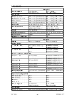
Page 9: ...0 ft OK 12 50 0 8 mm 0 030 in 5 kg 11 lb bobbin Drive roll 0 6 0 8 mm 0 023 in 0 030 in Cored Steel and Stainless wire installed on drive system Drive roll 0 8 1 0 mm 0 030 in 0 040 in Cored Steel and...

Page 10: ...15 A 90 A 18 5 V 40 duty cycle 150 A 21 5 V Breaker 15 A 100 A 19 V 25 duty cycle 205 A 24 25 V 20 duty cycle Breaker 20 A 130 A 20 5 V Setting range DC 15 A 14 75 V 230 A 25 5 V 15 A 14 75 V 130 A 20...

Page 11: ...pplication classification EM 215ic Voltage 230 V 1 50 60 Hz 120 V 1 50 60 Hz Primary current Imax GMAW MIG 30 A 27 6 A at 25 duty cycle Breaker 20 A 28 6 A Breaker 15 A 20 3 A Ieff GMAW MIG 14 A Break...

Page 12: ...C 14 to 104 F Enclosure class IP23S IP23S Application classification Duty cycle The duty cycle refers to the time as a percentage of a ten minute period that you can weld at a certain current without...

Page 13: ...ndustrial use In a domestic environment this product may cause radio interference It is the user s responsibility to take adequate precautions 4 1 Location Position the power source so that its coolin...

Page 14: ...AC 10 or 120 V 10 Too low supply voltage may cause poor welding performance Too high welding supply voltage will cause components to overheat and possibly fail Contact the local electric utility for i...

Page 15: ...A 30 A Maximum recommended fuse or circuit breaker rating Time delay fuse 30 A 30 A Maximum recommended fuse or circuit breaker rating 50 A 50 A Minimum recommended cord size 2 5 mm2 13 AWG 2 5 mm2 1...

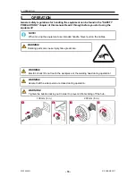
Page 16: ...the equipment NOTE When moving the equipment use intended handle Never pull on the cables WARNING Rotating parts can cause injury take great care WARNING Electric shock Do not touch the workpiece or t...

Page 17: ...cable 3 Knob for voltage selection EMP 11 Mains supply switch ON OFF 4 Main knob for menu navigation EMP 12 Gas valve inlet female 5 Torch Remote control connection 13 Knob for voltage selection EM 6...

Page 18: ...TIG accessories connect the TIG torch power cable to the negative terminal 6 see front illustration Connect gas inlet nut to a regulated shielding gas supply Connect the work return lead to the positi...

Page 19: ...0 8 mm 0 030 in wire If you use another diameter you must change the contact tip and drive roll The wire liner fitted in the torch is recommended for welding with Fe and SS wires 1 Open the side cover...

Page 20: ...moves smoothly through the wire guide Then set the pressure of the wire feeder s pressure rollers It is important that the pressure is not too high To check that the feed pressure is set correctly you...

Page 21: ...isual wire stamp designates the wire diameter groove in use 5 7 Shielding gas The choice of suitable shielding gas depends on the material Typically mild steel is welded with mixed gas Ar CO2 or 100 c...

Page 22: ...the power source operates at a 25 duty cycle it will provide the rated amperage for a maximum of 2 5 minutes out of every 10 minute period The remaining time 7 5 minutes the power source must be allo...

Page 23: ...lding power source has overheating protection that operates if the internal temperature becomes too high When this occurs the welding current is interrupted and an overheating symbol appears on the di...

Page 24: ...the equipment After power on has completed the main menu appears on the control panel 6 1 How to navigate EMP 215ic 1 Current Wire feed speed selection 2 Voltage selection 3 Menu navigation Rotate and...

Page 25: ...peed 6 Voltage 7 Dialogue box 6 1 4 Flux cored wire mode 1 Home screen 2 Information 3 Memory 4 Wire feed speed 5 Voltage 6 Dialogue box 6 1 5 MMA mode 1 Home screen 2 Information 3 Memory 4 Parameter...

Page 26: ...ation 6 Home screen 7 Dialogue box 6 1 8 User manual information 1 Maintenance information 2 Wear Spare parts 3 Operation information 4 Home screen 5 Dialogue box 6 1 9 Icon reference guide Home Spot...

Page 27: ...oot control 2T Trigger On OFF Burnback Adjusting the time when the voltage stays on after the wire feed is stopped to keep the wire from freezing in the weld puddle 4T Trigger Hold Lock User manual on...

Page 28: ...characteristics to stabilize the arc and reduce spatter when in the short circuit process Diagnostics Memory able to save welding programs for a specific application Language selection Stick electrode...

Page 29: ...e knob Adjust the voltage value in sMIG not functional 4 Knob for plate thickness or wire feed speed in sMIG mode outer circle in yellow plate thickness can be adjusted Wire feed speed can be adjused...

Page 30: ...reness of the disconnected power connections when performing work Detect and prevent premature reconnection of the power NOTE Perform maintenance more often during severe dusty conditions Before each...

Page 31: ...et wire outlet 2 or the feeder roller 3 are worn and need replacement See appendix WEAR PARTS for ordering numbers of parts 6 Remove and clean the feeder roller with a soft brush Clean the pressure ro...

Page 32: ...sure liner is the right size and type for wire Make sure the liner is not bent so that friction is caused between the liner and the wire MIG GMAW FCAW welding problems Make sure the MIG torch is conne...

Page 33: ...eaker is tripped Check that the input power welding and return cables are correctly connected Check that the correct current value is set Check the input power supply fuses The overheating protection...

Page 34: ...are designed and tested in accordance with international standards IEC EN 60974 1 IEC EN 60974 5 IEC EN 60974 7 IEC EN 60974 10 IEC EN 60974 12 and IEC EN 60974 13 It is the obligation of the authoriz...

Page 35: ...DIAGRAM 0463 408 001 35 ESAB AB 2017 DIAGRAM EMP 215ic EM 215ic...

Page 36: ...RING NUMBERS Ordering no Denomination Note 0700 300 985 EMP 215ic Bobbin 100 200 mm 4 8 in CE euro connection 0700 300 986 EM 215ic Bobbin 100 200 mm 4 8 in CE euro connection 0463 412 001 Spare parts...

Page 37: ...red 0 6 mm 0 8 mm 0 9 mm 1 2 mm 0 023 in 0 030 in 0 035 in 0 045 in 3 0191 496 114 Key drive shaft crescent N A N A 4 0367 556 001 Feed roll V groove Fe SS Flux Cored 0 6 mm 0 8 mm 0 023 in 0 030 in 0...

Page 38: ...WEAR PARTS 0463 408 001 38 ESAB AB 2017...

Page 39: ...CCESSORIES 0700 300 869 TIG Torch ET 17V 4 m TIG torch c w 8 pin plug 0700 200 004 MIG Torch MXL 270 3 m for FCW 1 2 mm 0459 366 887 Trolley W4014450 Foot control Contactor on off and current control...

Page 40: ...AB AB 2017 REPLACEMENTS PARTS Item Ordering no Denomination 1 0700 200 002 MIG Torch MXL 200 3 m 10 ft 3 0349 312 105 Gas hose 4 5 m 14 8 ft 4 0700 006 900 MMA welding cable kit 3 m 10 ft 5 0700 006 9...

Page 41: ...REPLACEMENTS PARTS 0463 408 001 41 ESAB AB 2017...

Page 42: ...Henares MADRID Tel 34 91 878 3600 Fax 34 91 802 3461 SWEDEN ESAB Sverige AB Gothenburg Tel 46 31 50 95 00 Fax 46 31 50 92 22 ESAB International AB Gothenburg Tel 46 31 50 90 00 Fax 46 31 50 93 60 SWI...

Reviews: