20
seCtIon 3
InstallatIon
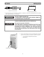
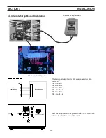
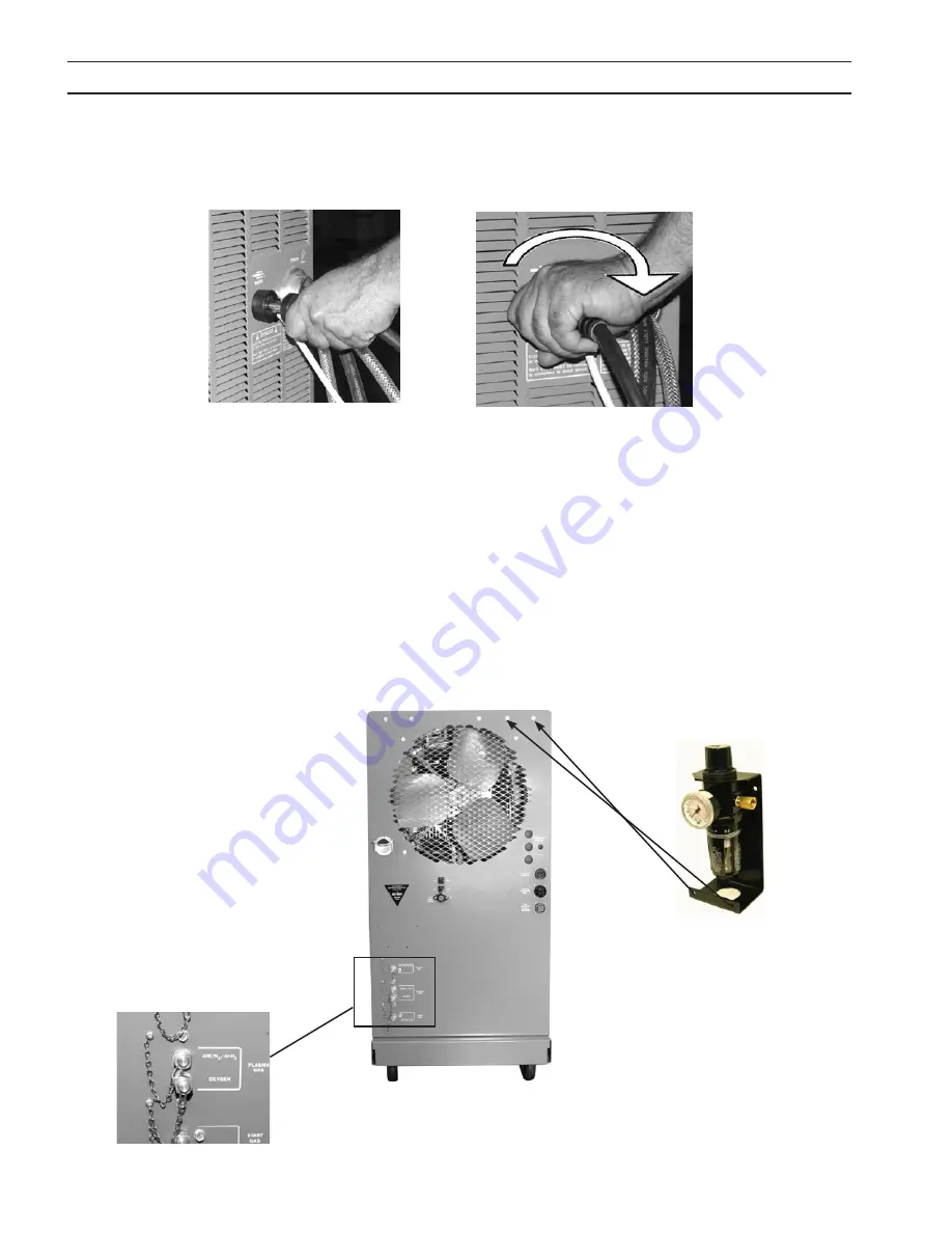
2. Re-install side panel.
3. Connect work cable to work connection on front panel.
Insert and rotate clockwise until tight. Approximately ½ turn.
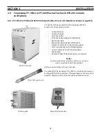
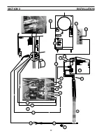
4. Assemble filter regulator and mounting bracket (P/N 30338) to the upper right corner on rear panel (as viewed from the
rear).
note:
A second filter/regulator can be mounted on the left.
5. Connect air hose assembly (P/N 678152) to filter regulator outlet fitting and to the N2/Air plasma gas fitting on the rear
panel.
note:
The air hose assembly has a left-hand threaded nut fitting on one end and a right-hand threaded nut on
the other.
6. Connect your air supply to the inlet port on filter regulator. (1/4 inch NPT female – customer supplied)
Summary of Contents for ESP-200
Page 1: ...ESP 200 Plasmarc Cutting System Instruction Manual F15 462 C 02 2008 ...
Page 12: ...12 section 2 description ...
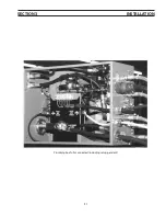
Page 31: ...31 section 3 installation Plumbing box fully connected including setup pendant ...
Page 32: ...32 CE 1 2 3 4 5 6 7 9 10 11 12 13 16 19 20 21 22 15 17 18 14 section 3 installation 8 ...
Page 84: ...84 section 7 replacement parts 1 2 3 4 5 6 7 8 9 10 11 12 13 7 6 Right Inside View ...
Page 88: ...88 section 7 replacement parts 6 1 4 5 6 R ef R ef 2 3 7 8 Back and Top Inside View ...
Page 92: ...92 section 7 replacement parts 1 2 3 4 5 6 7 8 7 10 Remote Setup Pendant P N 37145 ...
Page 100: ...100 notes ...


