background image

Instruction manual

0446 404 001 GB 20200806

Valid for: 008-xxx-xxxx

Fabricator EM 400i,
Fabricator EM 500i

Summary of Contents for Fabricator EM 400i

Page 1: ...Instruction manual 0446 404 001 GB 20200806 Valid for 008 xxx xxxx Fabricator EM 400i Fabricator EM 500i ...

Page 2: ...Mains supply 11 5 OPERATION 13 5 1 Connections and control devices 13 5 1 1 Welding control mode 15 5 2 Connection of welding and return cable 16 5 3 Symbols and functions 17 5 4 Thermal protection 17 5 5 Fan control 18 6 MAINTENANCE 19 6 1 Routine maintenance 19 6 2 Power source 19 7 TROUBLESHOOTING 21 8 ORDERING SPARE PARTS 24 BLOCK DIAGRAM 25 ORDERING NUMBERS 26 ACCESSORIES 27 Rights reserved t...

Page 3: ...ty precautions must meet the requirements that apply to this type of equipment The following recommendations should be observed in addition to the standard regulations that apply to the workplace All work must be carried out by trained personnel well acquainted with the operation of the equipment Incorrect operation of the equipment may lead to hazardous situations which can result in injury to th...

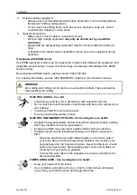
Page 4: ...o yourself and others Take precautions when welding and cutting ELECTRIC SHOCK Can kill Install and ground the unit in accordance with instruction manual Do not touch live electrical parts or electrodes with bare skin wet gloves or wet clothing Insulate yourself from work and ground Ensure your working position is safe ELECTRIC AND MAGNETIC FIELDS Can be dangerous to health Welders having pacemake...

Page 5: ...ngine before installing or connecting unit Keep hands hair loose clothing and tools away from moving parts FIRE HAZARD Sparks spatter can cause fire Make sure that there are no inflammable materials nearby Do not use on closed containers HOT SURFACE Parts can burn Do not touch parts bare handed Allow cooling period before working on equipment To handle hot parts use proper tools and or insulated w...

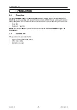
Page 6: ...ith powder filled cored wire FCAW S and welding with coated electrodes MMA The power sources are intended for use with the following wire feed units Feed 364 Fabricator Feed 364 ESAB accessories for the product can be found in the ACCESSORIES chapter of this manual 2 2 Equipment The power source is supplied with 5m return cable with earth clamp 4 5m mains cable instruction manual ...

Page 7: ...m current 0 93 Maximum input power at idle mode 50W Efficiency at maximum current 87 Open circuit voltage 63 7 V Operating temperature 10 to 40 C Transportation temperature 20 to 55 C Dimensions l w h 712 325 470 mm 28 1 12 8 18 5 in Weight 59 kg 130 lb Insulation class H Enclosure class IP 23S Application class Fabricator EM 500i Mains voltage 380 440 V 10 3 50 60 Hz Primary current I max 380 V 4...

Page 8: ...3S Application class Duty cycle The duty cycle refers to the time as a percentage of a ten minute period that you can weld or cut at a certain load without overloading The duty cycle is valid for 40 C 104 F or below Enclosure class The IP code indicates the enclosure class i e the degree of protection against penetration by solid objects or water Equipment marked IP23S is intended for indoor and o...

Page 9: ... by a professional CAUTION This product is intended for industrial use In a domestic environment this product may cause radio interference It is the user s responsibility to take adequate precautions 4 1 Location Position the power source so that cooling air inlets and outlets are not obstructed ...

Page 10: ...4 INSTALLATION 0446 404 001 10 ESAB AB 2020 4 2 Lifting instructions WARNING Secure the equipment particularly if the ground is uneven or sloping ...

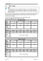
Page 11: ...he power source will automatically adjust to the supplied input voltage Recommended MCB sizes and minimum cable area Fabricator EM 400i Mains voltage 380 V 3 50 60 Hz 400 V 3 50 60 Hz 415 V 3 50 60 Hz 440 V 3 50 60 Hz Mains cable area 4 6 mm 4 6 mm 4 6 mm 4 6 mm Maximal current rating Imax 28 A 27 A 25 A 21 A I1eff MIG MAG 20 A 19 A 18 A 17 A MMA 21 A 20 A 19 A 18 A Input circuit breaker MCB distr...

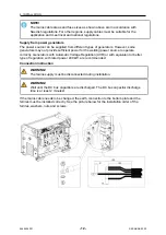
Page 12: ...er for the welding power source to operate correctly Generators with Automatic Voltage Regulation AVR or with equivalent or better type of regulation with rated power 40 kW are recommended Connection instruction WARNING The mains supply must be disconnected during installation WARNING Wait until the DC bus capacitors are discharged The DC bus capacitor discharge time is at least 2 minutes If the m...

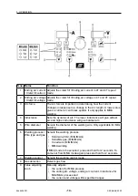
Page 13: ...ation 5 1 Connections and control devices 1 Connection MIG MAG Welding cable MMA Welding cable or return cable 6 Fuse for the gas heater input supply 2 2 Connection MIG MAG Return cable MMA Return cable or welding cable 7 Mains power supply switch ON OFF 3 3 Indicating LED Overheating 8 Mains cable inlet 4 Connection of wire feed unit 9 110V AC power supply socket for gas heater 5 Circuit breaker ...

Page 14: ... arc The lower inductance will give softest arc and higher inductance will give hardest arc 5 Wire diameter Selects the diameter of the welding wire Only applicable for MIG welding 6 Welding process Wire type and gas Selects the welding process Solid wire CO2 MIG MAG Solid Mix gas MIG MAG Cored wire MIG MAG MMA welding If MMA mode to be selected press and hold for 2 seconds To come out from MMA mo...

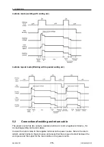
Page 15: ...ltage and current Releasing the trigger switch stops the welding and gas post flow starts 4 stroke repeat When the torch trigger switch is pressed in the gas flow starts and an arc is generated When the trigger switch is released the arc generation is locked When the trigger switch is pressed in again the ending arc is generated using the ending arc voltage and current When the switch is released ...

Page 16: ...n cable The power source has two outputs a positive terminal and a negative terminal for connecting welding and return cables Connect the return cable to the negative terminal on the power source Secure the return cable s contact clamp to the work piece and ensure that there is good contact between the work piece and the output for the return cable on the power source ...

Page 17: ... Voltage drop 10m 100 60 35 50 250 A 280 A 320 A 0 352 V 100 A 70 310 A 350 A 420 A 0 254 V 100 A 95 375 A 440 A 530 A 0 189 V 100 A 5 3 Symbols and functions Mains power supply switch Overheating 3 Protective earth Positioning of lifting eye Arc force Inductance Gas detection MMA welding Ending arc current Crater fill current Ending arc voltage Crater fill voltage 5 4 Thermal protection The weldi...

Page 18: ...urrent is less than 200A the fan will run at low speed if the welding current goes above 200A the fan will run at high speed In Fabricator EM 500i when the welding current is less than 300A the fan will run at low speed if the welding current goes above 300A the fan will run at high speed After the welding stops the fan will continue to run for 10 minutes and the power source switches to idle mode...

Page 19: ...r safe and reliable operation NOTE Perform maintenance more often during severe dusty conditions Before each use make sure that Product and cables are not damaged The torch is clean and not damaged 6 1 Routine maintenance Maintenance schedule during normal conditions Check equipment prior to every use Interval Area to maintain Every 3 months Clean or replace unreadable labels Clean weld terminals ...

Page 20: ... 4 Remove the plastic cover between the heat sink and fan b 5 Clean the power source with dry compressed air 4 bar as follows The upper rear part From the rear panel through the secondary heat sink The inductor transformer and current sensor The power components side from the rear side behind PCB15AP1 The PCBs at both sides 6 Make sure that there is no dust left on any part of the power source 7 I...

Page 21: ... fault When the equipment is turned on the welding torch trigger switch is on the switch may be faulty Turn off the switch Replace the welding torch E2 E2 None Output terminal over temperature The OKC terminal and welding cable is not connected properly The copper cross sectional area of the output power cable is too small The output cable OKC fails to meet the specification requirement The fan do...

Page 22: ...hat the fan blades are not stuck with any foreign objects that the fan blades are not stuck with any foreign objects E5 E5 1 8 Button error Button is not working Button does not rebound after being pressed Check the button and make sure it does not stick E6 E6 None Output overcurrent The output is short circuited or the current is too high Verify that the output is not short circuited E7 E7 None I...

Page 23: ...the mains power supply switch is turned on Check that the mains welding and return cables are correctly connected Check that the correct current value is set Check the mains power supply fuses The welding current is interrupted during welding Check whether the thermal protection trip has operated indicated by the orange LED on the front The thermal protection trips frequently Make sure that you ar...

Page 24: ...ernational standard GB T 15579 1 IEC 60974 1 On completion of service or repair work it is the responsibility of the person s performing the work to ensure that the product still complies with the requirements of the above standards Spare parts and wear parts can be ordered through your nearest ESAB dealer see esab com When ordering please state product type serial number designation and spare par...

Page 25: ...BLOCK DIAGRAM 0446 404 001 25 ESAB AB 2020 BLOCK DIAGRAM ...

Page 26: ...ERING NUMBERS Ordering number Denomination Type Notes 0700 020 001 Power source Fabricator EM 400i CCC 0700 020 002 Power source Fabricator EM 500i CCC 0446 575 001 Spare parts list Technical documentation is available on the Internet at www esab com ...

Page 27: ...inter connection cable 0349 490 607 15m 70mm2 inter connection cable 0349 490 606 25m 70mm2 inter connection cable 0349 305 138 5m 50mm2 inter connection cable 0349 305 357 10m 50mm2 inter connection cable 0349 305 355 15m 50mm2 inter connection cable 0349 305 356 25m 50mm2 inter connection cable 0465 416 880 Wheel Kit 0349 313 450 Trolley compatible with Fabricator Feed 364 ...

Page 28: ...For contact information visit esab com ESAB AB Lindholmsallén 9 Box 8004 402 77 Gothenburg Sweden Phone 46 0 31 50 90 00 http manuals esab com ...

Reviews: