33
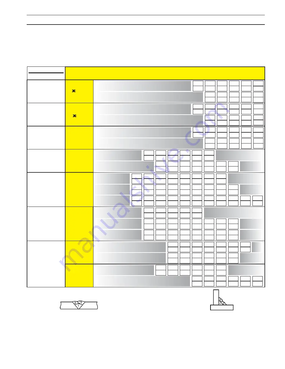
table 3 - MIg paraMeters chart
sectIon 4
operatIon
Polarity - DCEP
(Electrode Positive)
Polarity - DCEP
(Electrode Positive)
280
21
250
21
230
21
195
20
185
19.5
.030
.8mm
400
25
475
26
450
25.5
350
22
325
22
300
21
230
21
180
20
.035
.9mm
475
26
450
25.5
400
25
350
22
325
22
300
21
230
21
180
20
.045
.9mm
STAINLESS
STEEL
Arcaloy
308L, LSi, H
309L, LSi, H
316L, LSi, H
Shield Gas
Shield Gas
Shield Gas
Shield Gas
Helium TriMix
For thicknesses
above 3/16” use
98% Argon - 2% CO
2
75% Argon/25% CO
2
75% Argon/25% CO
2
100% CO
2
500
19
400
18
330
17
280
16
230
16
180
15
130
15
90
14
.030
.8mm
400
20
360
19
320
18
280
17
240
17
200
16
160
16
120
15
85
15
.035
.9mm
270
23
270
23
240
22
220
21
200
20
180
19
160
19
140
18
120
17
100
16
80
16
.045
1.2mm
CARBON
STEEL
Spoolarc 82
Spoolarc 85
Spoolarc 87
Spoolarc 86
Polarity - DCEP
(Electrode Positive)
520
26
500
26
430
25
400
24
380
24
320
23
265
22
430
28
370
27
350
26
320
26
290
26
215
24
.035
Spool Gun
.9mm
3/64”
Standard Gun
1.2mm
ALUMINUM
4000 Series
400
26
400
26
380
25
320
25
280
23
220
22
680
23
600
23
550
23
440
22
400
22
375
21
.035
Spool Gun
.9mm
3/64”
Standard Gun
1.2mm
ALUMINUM
5000 Series
100% Argon
Shield Gas
For 100% CO
2
add 2 volts
Wire Feed Speed
Volts
700
28
600
27
460
26
380
25
280
22
.035”
.9
mm
500
33
400
30
300
29
200
28
.045”
1.2
mm
CORED WIRE
Dual Shield
7100 Ultra
7100 LC
FC 717
.045”
1.2
mm
.045”
1.2
mm
.052”
1.4
mm
.052”
1.4
mm
Argon-25% CO
2
or 100% CO
2
as recommended in
product data sheet
Polarity - DCEP
(Electrode Positive)
Polarity - DCEP
(Electrode Positive)
Polarity - DCEP
(Electrode Positive)
Polarity - DCEN
(Electrode Negative)
360
17
220
17
200
24
200
23
250
25
275
24
200
25
175
23
300
26
350
25
300
26
250
24
425
29
450
26
400
28
300
25
475
30
500
27
450
29
350
26
550
30
600
29
785
29
500
30
400
27
550
33
170
17
150
16
110
16
80
15
.035”
.9
mm
Self-Shielding
CORED WIRE
No Shield Gas
Required
22ga.
.030”
.8mm
18ga.
.048”
1.2mm
16ga.
.060”
1.5mm
14ga.
.075”
1.9mm
12ga.
.105”
2.7mm
10ga.
.135”
3.5mm
11ga.
1/8”
3.2mm
3/16”
4.8mm
1/4”
6.4mm
5/16”
8.0mm
3/8”
9.6mm
1/2” Up
12mm
Gauge
Inches
Metric
Material
Thickness
Table Legend
20ga.
.036”
.9mm
Material Thickness
Type
STAINLESS STEEL
CARBON STEEL &
22ga.
.030”
.8mm
18ga.
.048”
1.2mm
16ga.
.060”
1.5mm
14ga.
.075”
1.9mm
12ga.
.105”
2.7mm
10ga.
.135”
3.5mm
11ga.
1/8”
3.2mm
3/16”
4.8mm
1/4”
6.4mm
5/16”
8.0mm
3/8”
9.6mm
Gauge
Inches
Metric
20ga.
.036”
.9mm
35
45
55
75
85
95 110 130 185 225 250
65-75
Sureweld 10P
Sureweld SW-15
Sureweld SW-15IP
Sureweld 7024
Atom Arc7018
Arcaloy 308L
Electrode
E6010
CARBON STEEL
E7018
E7024
E7014
E6013
E308L
60-90
120-135
150-210
130-170
80-110
145-190 170-230
70-100 100-150 160-200 190-270
130-180 180-240 250-270
70-100
90-160 130-220 200-270
40-70
70-100 100-145 130-190
STAINLESS STEEL
3/32
(2.4)
1/8
(3.2)
5/32
(4.0)
3/16
(4.8)
Inches
(mm)
Diameter
Type
130
18
130
18
125
18
100
17
80
16
70
16
54
15
.045”
1.2
mm
300
MultiMaster
00.0
125
2
1
4
3
300
MultiMaster
00.0
080
2
1
3
4
MIG - DCEN
Electrode
Negative
TIG - DCEN
Electrode
Negative
STICK - DCEP
Electrode
Positive
MIG - DCEP
Electrode
Positive
19.2
185
3
4
1
2
300
MultiMaster
CORED WIRE
Dual Shield
Series
710X
II 711X
CORED WIRE
Dual Shield
Series
II 712X
1. Determine initial settings from TIG Data Table based on material
thickness.
2. Place
WELD PROCESS
switch to the TIG (left) position.
3. While holding the
PRESET
button, adjust the
CURRENT
knob to set desired weld current in the upper digital display window.
4. Touch the tungsten electrode to the workpiece momentarily to
establish the arc. Adjust the welding current as needed for the
desired puddle control.
Note: The
WIRE SPEED
knob has no effect in TIG mode.
1
2
3
4
TIG SET-UP
1. Determine initial settings from Stick Electrode Data Table based
on electrode type and diameter.
2. Place the
WELD PROCESS
switch to the STICK (right) position.
3. While holding the
PRESET
button, adjust the
CURRENT
knob to set the desired weld current in the upper digital display
window.
4. Strike the electrode and start welding. Adjust the welding current as
needed for the desired puddle control.
Note: The
WIRE SPEED
knob has no effect in STICK mode.
1
2
3
4
STICK SET-UP
Welding Polarity - DCEP
(Electrode Positive)
Welding Polarity - DCEN
(Electrode Negative)
Shielding gas flow rate
15 - 25 cfh
When the WELD PROCESS switch is set to TIG or STICK position, the electrode will be electrically “
HOT
”.
When the WELD PROCESS is set to the MIG position, depressing the gun trigger will cause the wire
electrode to become electrically “
HOT
” and will start the feed motor to feed wire.
Do not allow the electrode to touch the work until you are ready to make a weld.
POLARITY CONNECTION GUIDE
1. Determine initial settings from MIG Data Table based on wire
type, diameter, material thickness and shielding gas.
2. Place
WELD PROCESS
switch to MIG (center) then press
PRESET
button.
3. Turn the
WIRE SPEED
knob to set desired speed in the
upper digital display window.
4. Turn the
VOLTAGE
knob to set desired voltage in the lower
digital display.
5. Pull gun trigger and start welding. Fine tune wire speed and
volts as needed for desired arc characteristics.
MIG/FCAW SET-UP
Note 1: MIG 3/8" and above setting data indicates multi-pass weld sequence with proper joint preparation required.
Note 2: FCAW above 1/2" setting data indicates multi-pass weld sequence with proper joint preparation required.
1
2
3
4
LABEL Part No. 0558954112 Rev OR - 9/07
(Refer to Instruction Literature 0558007770 for more detailed information regarding Safety, Installation, and Operation)
CoreShield 11
(Multi Pass)
CoreShield 15
(Single Pass)
MIG/FCAW
MIG/FCAW
MIG/FCAW
Use only recommended joint preparation and weld sequence
procedures found in AWS, ANSI, ASME, ASNT publications and codes.
Summary of Contents for Multimaster 300
Page 1: ...Multimaster300 300X MIG TIG STICK WELDING PACKAGE 0558007770 06 2010 Instruction Manual...
Page 4: ...4 table of contents...
Page 40: ...40 TABLE DES MATI RES...
Page 66: ...66 section 6 replacement parts...
Page 67: ...67 section 6 replacement parts 26...
Page 68: ...68 section 6 replacement parts...
Page 69: ...69 section 6 replacement parts...
Page 70: ...70 section 6 replacement parts...
Page 71: ...71 section 6 replacement parts...
Page 72: ...72 section 6 replacement parts...
Page 73: ...73 section 6 replacement parts...
Page 74: ...74 section 6 replacement parts...
Page 75: ...75 section 6 replacement parts...
Page 76: ...76 section 6 replacement parts Mulitmaster 300 Mulitmaster 300X...
Page 77: ...77 section 6 replacement parts Mulitmaster 300 Mulitmaster 300X...
Page 78: ...78 section 6 replacement parts Mulitmaster 300 Mulitmaster 300X...
Page 79: ...79 section 6 replacement parts Mulitmaster 300 Mulitmaster 300X...
Page 80: ...80 section 6 replacement parts Mulitmaster 300 Mulitmaster 300X...
Page 81: ...81 section 6 replacement parts Mulitmaster 300 Mulitmaster 300X...
Page 84: ...section 6 replacement parts...


