background image

- 5 -

US warninga

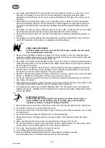
2. Use a face shield fitted with the correct filter and cover plates to protect your eyes, face, neck

and ears from sparks and rays of the arc when operating or observing operations. Warn
bystanders not to watch the arc and not to expose themselves to the rays of the electric-arc or
hot metal.

3. Wear flameproof gauntlet type gloves, heavy long-sleeve shirt, cuffless trousers, high-topped

shoes and a welding helmet or cap for protection, to protect against arc rays and hot sparks or
hot metal. A flameproof apron may also be desirable as protection against radiated heat and
sparks.

4. Hot sparks or metal can lodge in rolled up sleeves, trouser cuffs, or pockets. Sleeves and collars

should be kept buttoned and open pockets eliminated from the front of clothing.

5. Protect other personnel from arc rays and hot sparks with a suitable nonflammable partition or

curtains.

6. Use goggles over safety glasses when chipping slag or grinding. Chipped slag may be hot and

can fly far. Bystanders should also wear goggles over safety glasses.

FIRES AND EXPLOSIONS
Heat from flames and arcs can start fires. Hot slag or sparks can also cause
fires and explosions. Therefore:

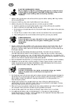
1. Remove all combustible materials well away from the work area or cover the materials with a

protective nonflammable covering. Combusible materials include wood, clot, sawdust, liquid and
gas fuels, solvents, pants and coatings papper, etc.

2. Hot sparks or hot metal can fall through cracks or crevices in floors or wall openings and cause a

hidden smoldering fire or fires on the floor below. Make certain that such openings are protected
from hot sparks and metal.

3. Do not weld, cut or perform other hot work until the workpiece has been completely cleaned so

that there are no substances on the workpiece which might produce flammable or toxic vapors.
Do not do hot work on closed containers. They may explode.

4. Have fire extinguishing equipment handy for instant use, such as a garden hose, water pail, sand

bucket, or portable fire extinguisher. Be sure you are trained in its use.

5. Do not use equipment beyond its ratings. For example, overloaded welding cable can overheat

and create a fire hazard.

6. After completing operations, inspect the work area to make certain there are no hot sparks or hot

metal which could cause a later fire. Use fire watchers when necessary.

7. For additional information refer to NFPA Standard 51B, “Fire Prevention in Use of Cutting and

Welding Processes”, available from the National Fire Protection Association, Batterymarch Park,
Quincy, MA 02269.

ELECTRICAL SHOCK
Contact with live electrical parts and ground can cause severe injury or
death. DO NOT use AC welding current in damp areas, if movement is

confined, or if there is danger of falling. Therefore:

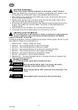
1. Be sure the power source frame (chassis) is connected to the ground system of the input power.
2. Connect the workpiece to a good electrical ground.
3. Connect the work cable to the workpiece. A poor or missing connection can expose you or others

to a fatal shock.

4. Use well-maintained equipment. Replace worn or damaged cables.
5. Keep everything dry, including clothing, work area, cables, torch/electrode holder and power

source.

6. Make sure that all parts of your bady are insulated from work and from ground.
7. Do not stand directly on metal or the earth while working in tight quarters or a damp area; stand

on dry boards or an insulating platform and wear rubber-soled shoes.

8. Put on dry, hole-free gloves before turning on the power.
9. Turn off the power before removing your gloves.
10. Refer to ANSI/ASC Standard Z49.1 (listed on next page) for specific grounding

recommendations. Do not mistake the work lead for a ground cable.

US

Summary of Contents for Origo Mig 410

Page 1: ...US FR ES Valid for serial no 627 xxx xxxx 122 xxx xxxx 0463 315 031 US FR ES 20111205 Origo Mig 410 Mig 510 Manuel d instructions Instrucciones de uso Instruction manual ...

Page 2: ...us réserve de modifications sans avis préalable Reservado el derecho de cambiar las especificaciones sin previo aviso Rights reserved to alter specifications without notice AMERICAN 3 FRANÇAIS 17 ESPAÑOL 31 ...

Page 3: ...A 9 5 INSTALLATION 9 5 1 Location 10 5 2 Assembly of components 10 5 3 Assembly of counter balance 11 5 4 Electrical installation 12 5 5 Mains power supply 12 6 OPERATION 14 6 1 Connection and control devices 14 6 2 Start 15 6 3 Overheating protection 15 6 4 Idle mode 15 6 5 Inductance 15 7 MAINTENANCE 15 7 1 Inspection and cleaning 15 8 FAULT TRACING 16 9 ORDERING OF SPARE PARTS 16 SCHEMATIC DIAG...

Page 4: ...essary the manufacturer recommends that a telephone or written request for service advice be made to the Authorized Distributor from whom it was purchased This equipment or any of its parts should not be altered without the prior written approval of the manufacturer The user of this equipment shall have the sole responsibility for any malfunction which results from improper use faulty maintenance ...

Page 5: ...ere are no substances on the workpiece which might produce flammable or toxic vapors Do not do hot work on closed containers They may explode 4 Have fire extinguishing equipment handy for instant use such as a garden hose water pail sand bucket or portable fire extinguisher Be sure you are trained in its use 5 Do not use equipment beyond its ratings For example overloaded welding cable can overhea...

Page 6: ...ses 3 If you develop momentary eye nose or throat irritation while operating this is an indication that ventilation is not adequate Stop work and take necessary steps to improve ventilation in the work area Do not continue to operate if physical discomfort persists 4 Refer to ANSI ASC Standard Z49 1 see listing below for specific ventilation recommendations 5 WARNING This product when used for wel...

Page 7: ...n on safe practices for electric arc welding and cutting equipment ask your supplier for a copy of Precautions and Safe Practices for Arc Welding Cutting and Gouging Form 52 529 The following publications which are available from the American Welding Society 550 N W LeJuene Road Miami FL 33126 are recommended to you 1 ANSI ASC Z49 1 Safety in Welding and Cutting 2 AWS C5 1 Recommended Practices fo...

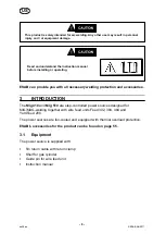
Page 8: ...ccessories 3 INTRODUCTION The Mig 410 and Mig 510 are step controlled power sources designed for MIG MAG welding together with wire feed units Feed 302 304 484 and YardFeed 200 The power sources are fan cooled and equipped with thermal overload protection ESAB s accessories for the product can be found on page 55 3 1 Equipment The power source is supplied with S 5m return cable with return clamp S...

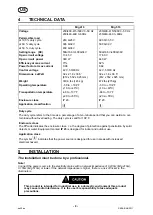
Page 9: ...osure class IP 23 IP 23 Application classification Duty cycle The duty cycle refers to the time as a percentage of a ten minute period that you can weld at a cer tain load without overloading The duty cycle is valid for 104 F Enclosure class The IP code indicates the enclosure class i e the degree of protection against penetration by solid objects or water Equipment marked IP 23 is designed for in...

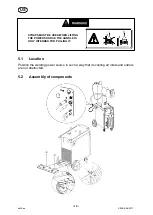
Page 10: ...UST BE USED WHEN LIFTING THE POWER SOURCE THE HANDLE IS ONLY INTENDED FOR PULLING IT 5 1 Location Position the welding power source in such a way that its cooling air inlets and outlets are not obstructed 5 2 Assembly of components US ...

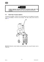
Page 11: ...WHEELS IN THEIR REAR POSITION 5 3 Assembly of counter balance Assemble the stabiliser CB KIT if the counter balance is to be installed on the power source The stabiliser CB KIT is an accessory The order number can be found on page 55 Attention Using the counter balance without stabiliser may cause the power source to tip over US ...

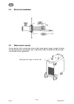
Page 12: ...ins power supply Check that the unit is connected to the correct mains power supply voltage and that it is protected by the correct fuse size A protective earth connection must be made in accordance with regulations Rating plate with supply connection data US ...

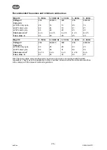
Page 13: ... 4 x 2 5 Fuse slow A 25 20 20 25 20 Mig 510 3 50 Hz 3 50 60 Hz 3 50 Hz 3 60 Hz 3 60 Hz Voltage V 230 400 415 500 230 440 460 Current A at 100 duty cycle 43 25 20 43 23 at 60 duty cycle 68 39 31 68 35 Cable area mm2 4 x 16 4 x 6 4 x 6 4 x 16 4 x 6 Fuse slow A 63 35 35 63 25 NB The mains cable areas and fuse sizes as shown above are in accordance with Swedish regulations They may not be applicable i...

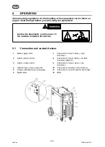
Page 14: ...G 6 1 Connection and control devices 1 Mains supply switch 7 Connection for return cable high inductance 2 Switch precise control 8 Connection for return cable medium inductance Mig 510 3 Switch coarse control 9 Connection for return cable low inductance 4 Indicator lamp power supply ON 10 Connection for welding current cable 5 Orange indicating lamp overheating 11 Connection for control cable for...

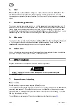
Page 15: ...e The fan switches off 5 min after welding has finished or 5 min after running at a decreased speed without welding Once the fan has switched off the power supply lamp on the front panel flashes 6 5 Inductance Higher inductance produces a more flowing weld and less spatter Lower inductance produces a harsher sound and a stable concentrated arc 7 MAINTENANCE Regular maintenance is important for saf...

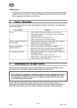
Page 16: ...ters are clogged S Make sure that you are not exceeding the rated data for the power source i e that the unit is not being overloaded Poor welding performance S Check that the welding current supply and return cables are correctly connected S Check that the correct current value is set S Check that the correct welding wires are being used S Check the main power supply fuses 9 ORDERING OF SPARE PAR...

Page 17: ...ontrepoids 25 4 4 Installation électrique 26 4 5 Alimentation secteur 26 5 FONCTIONNEMENT 28 5 1 Appareils de contrôle et de connexion 28 5 2 Démarrer 28 5 3 Protection anti surchauffe 29 5 4 Mode inactif 29 5 5 Inductance 29 6 ENTRETIEN 29 6 1 Contrôle et nettoyage 29 7 DÉPANNAGE 30 8 COMMANDE DE PIÈCES DE RECHANGE 30 SCHÉMA 48 INSTRUCTIONS DE BRANCHEMENT 52 NUMÉRO DE RÉFÉRENCE 54 ACCESSOIRES 55 ...

Page 18: ...r des étincelles et du rayonnement thermique 4 Les étincelles ou projections de métal en fusion risquent de se loger dans les manches retroussées les bords relevés de pantalons ou dans les poches Il convient donc de boutonner complètement les manches et le col et de porter des vêtements sans poches à l avant 5 Protéger du rayonnement de l arc et des étincelles les personnes se trouvant à proximité...

Page 19: ... Éviter tout contact direct avec du métal ou la masse lors de travaux dans des endroits exigus et en zone humide se tenir sur des panneaux ou sur une plate forme isolante et porter des chaussures à semelles en caoutchouc 8 Enfiler des gants secs et sans trous avant de mettre l équipement sous tension 9 Mettre l équipement hors tension avant de retirer les gants 10 Voir la norme ANSI ASC Z49 1 voir...

Page 20: ...nt réglée par un détendeur adapté au type de bouteille utilisée Ne pas utiliser d adaptateurs Garder les tuyaux et accessoires en bon état Pour le montage du détendeur sur une bouteille de gaz comprimé suivre les instructions du fabricant 2 Fixer les bouteilles verticalement au moyen d une chaîne ou d une sangle à un chariot à bras un châssis de roulement un banc un mur un piquet ou un rack Ne jam...

Page 21: ... for Plasma Arc Welding 3 AWS C5 2 Recommended Practices for Plasma Arc Cutting 4 AWS C5 3 Recommended Practices for Air Carbon Arc Gouging and Cutting 5 AWS C5 5 Recommended Practices for Gas Tungsten Arc Welding 6 AWS C5 6 Recommended Practices for Gas Metal Arc welding 7 AWS SP Safe practices Réédition Manuel de soudage 8 ANSI AWS F4 1 Recommended Safe Practices for Welding and Cutting of Conta...

Page 22: ...CTION Le Mig 410 et le Mig 510 sont des machines de soudage a commutateur conçus pour le soudage MIG MAG avec les dévidoirs Feed 302 304 484 et YardFeed 200 Les générateurs sont refroidis par ventilateur et équipés d une protection contre la surchauffe Voir les accessoires ESAB en page 55 2 1 Équipement Le générateur est fourni avec S un câble de retour de 5 m avec pince de retour S une console po...

Page 23: ... 23 Catégorie d application Facteur de marche Le facteur d intermittence est le temps exprimé en pourcentage d une période de 10 minutes pen dant lequel il est possible de souder ou de couper à une charge déterminée Le facteur de marche est valable à 40 C Classe de protection Le code IP indique la classe de protection c est à dire le degré d étanchéité à l eau et aux particules solides Les machine...

Page 24: ...domestiques ce produit peut provoquer des interférences parasitaires C est la responsabilité de l utilisateur de prendre les précautions adéquates 4 1 Emplacement Placez le générateur de soudage de manière à ne pas obstruer les entrées et sorties d air de refroidissement 4 2 Assemblage des composants FR ...

Page 25: ... en position arrière 4 3 Montage du contrepoids Montez l ensemble stabilisateur KIT CB si le contrepoids doit être installé sur le géné rateur L ensemble stabilisateur KIT CB est un accessoire La référence de com mande se trouve à la page 55 Attention L utilisation du contrepoids sans stabilisateur pourrait provoquer le renversement du générateur FR ...

Page 26: ...e générateur est connecté à une tension d alimentation secteur adaptée et qu il est protégé par un fusible de calibre adéquat Pour des raisons de protection l équipement doit être relié à la terre conformément aux réglementations en vigueur Plaque signalétique avec informations de connexion FR ...

Page 27: ...le lent A 25 20 20 25 20 Mig 510 3 50 Hz 3 50 60 Hz 3 50 Hz 3 60 Hz 3 60 Hz Tension V 230 400 415 500 230 440 460 Intensité A pour un facteur de marche de 100 43 25 20 43 23 pour un facteur de marche de 60 68 39 31 68 35 Section câbles 2 mm 4 x 16 4 x 6 4 x 6 4 x 16 4 x 6 Fusible lent A 63 35 35 63 25 Remarque La section des câbles secteur et les calibres de fusibles mentionnés ci dessus sont conf...

Page 28: ...exion pour câble de retour inductance moyenne Mig 510 3 Interrupteur commande générale 9 Connexion pour câble de retour faible inductance 4 Témoin lumineux alimentation ON 10 Connexion pour câble de retour 5 Témoin lumineux de surchauffe 11 Connexion du câble de commande du dévidoir 6 Instrument numérique V A 12 MCB 5 2 Démarrer Lorsqu ils sont mis en marche les témoins restent allumés pendant 2 s...

Page 29: ... projections Un niveau d inductance bas produit un bruit plus aigu mais l arc qui en résulte est stable et concentré 6 ENTRETIEN Un entretien régulier garantit la sécurité et la fiabilité du matériel PRUDENCE La garantie du fabricant cesse d être valable si le matériel a été ouvert par l utilisateur pendant la période de garantie pour réparer quelque panne que ce soit 6 1 Contrôle et nettoyage Gén...

Page 30: ...ance nominale du générateur n est pas dépassée et qu il n y a pas de surcharge de l unité Soudage de qualité médiocre S Vérifiez la connexion du câble d alimentation de soudage et des câbles de retour S Vérifiez le réglage de la tension S Vérifiez que les fils de soudage utilisés sont adaptés S Vérifiez les fusibles de l alimentation secteur 8 COMMANDE DE PIÈCES DE RECHANGE Les interventions élect...

Page 31: ...4 Instalación eléctrica 40 4 5 Alimentación eléctrica 40 5 FUNCIONAMIENTO 42 5 1 Conexiones y dispositivos de control 42 5 2 Puesta en marcha 43 5 3 Protección contra el sobrecalentamiento 43 5 4 Modo de reposo 43 5 5 Inductancia 43 6 MANTENIMIENTO 43 6 1 Revisión y limpieza 44 7 SOLUCIÓN DE PROBLEMAS 44 8 PEDIDOS DE REPUESTOS 45 ESQUEMA 48 INSTRUCCIONES DE CONEXIÓN 52 REFERENCIA DE PEDIDO 54 ACCE...

Page 32: ...s mangas enrolladas de la camisa el ruedo del pantalón o los bolsillos Mangas y cuellos deberán mantenerse abotonados bolsillos al frente de la camisa deberán ser cerrados o eliminados 5 Proteja a otras personas de los rayos del arco y chispas calientes con una cortina adecuada no flamable como división 6 Use careta protectora además de sus gafas de seguridad cuando esté removiendo escoria o pulie...

Page 33: ...ntorchas pinza del electrodo y la fuente de poder 6 Asegúrese que todas las partes de su cuerpo están insuladas de ambos la pieza de trabajo y tierra 7 No se pare directamente sobre metal o tierra mientras trabaja en lugares estrechos o áreas húmedas trabaje sobre un pedazo de madera seco o una plataforma insulada y use zapatos con suela de goma 8 Use guantes secos y sin agujeros antes de energiza...

Page 34: ...n la ventilación 5 ADVERTENCIA Este producto cuando se utiliza para soldaduras o cortes produce humos o gases los cuales contienen químicos conocidos por el Estado de California de causar defectos en el nacimiento o en algunos casos Cancer California Health Safety Code 25249 5 et seq MANEJO DE CILINDROS Los cilindros si no son manejados correctamente pueden romperse y liberar violentamente gases R...

Page 35: ...es for Arc Welding Cutting and Gouging Form 52 529 Las siguientes publicaciones disponibles através de la American Welding Society 550 N W LeJuene Road Miami FL 33126 son recomendadas para usted 1 ANSI ASC Z49 1 Safety in Welding and Cutting 2 AWS C5 1 Recommended Practices for Plasma Arc Welding 3 AWS C5 2 Recommended Practices for Plasma Arc Cutting 4 AWS C5 3 Recommended Practices for Air Carbo...

Page 36: ...iseñadas para soldadura MIG MAG en combinación con las unidades de alimentación de hilo Feed 302 304 484 y YardFeed 200 Las fuentes de corriente van refrigeradas por ventilador y disponen de protección contra las sobrecargas térmicas Si desea obtener más información sobre los accesorios ESAB para este producto consulte la página 55 2 1 Equipo La fuente de corriente se suministra con los siguientes...

Page 37: ...a El factor de intermitencia especifica el porcentaje de tiempo de un período de diez minutos durante el cual es posible soldar o cortar con una determinada carga El factor de intermitencia es válido para 40 C Grado de estanqueidad El código IP indica el grado de estanqueidad es decir el nivel de protección contra la penetración de objetos sólidos y agua Los aparatos marcados IP 23 están destinado...

Page 38: ...mentación utilice el cáncamo de suspensión El tirador sólo debe utilizarse para arrastrarla 4 1 Ubicación Coloque la fuente de corriente de soldadura de forma que no queden obstruidas las entradas y salidas del aire de refrigeración 4 2 Montaje de los componentes ES ...

Page 39: ... utilizarla eche las ruedas hacia atrás 4 3 Montaje del contrapeso Monte el estabilizador CB KIT si va a instalar el contrapeso en la fuente de corriente El estabilizador CB KIT es un accesorio El códe referencia se encuentra en la página 55 Precaución Usar el contrapeso sin estabilizador puede motivar que vuelque la fuente de corriente ES ...

Page 40: ...eléctrica Compruebe que la unidad reciba la tensión eléctrica adecuada y que esté correctamente protegida con un fusible del tamaño adecuado De acuerdo con la normativa es necesario contar con una toma de tierra de protección Placa con los datos de conexión eléctrica ES ...

Page 41: ...ntes A 25 20 20 25 20 Mig 510 3 50 Hz 3 50 60 Hz 3 50 Hz 3 60 Hz 3 60 Hz Tensión V 230 400 415 500 230 440 460 Corriente A a un ciclo de trabajo del 100 43 25 20 43 23 a un ciclo de trabajo del 60 68 39 31 68 35 Sección del cable mm2 4 x 16 4 x 6 4 x 6 4 x 16 4 x 6 Fusible contra sobrecorrientes A 63 35 35 63 25 Nota Los tamaños de fusible y las secciones del cable eléctrico que se indican en la t...

Page 42: ...nmutador de alimentación de red 7 Conexión del cable de retorno alta inductancia 2 Interruptor control preciso 8 Conexión del cable de retorno media inductancia Mig 510 3 Interruptor control ordinario 9 Conexión del cable de retorno baja inductancia 4 Indicador luminoso alimentación ON 10 Conexión para cable de corriente de soldadura 5 Indicador luminoso naranja sobrecalentamiento 11 Conexión para...

Page 43: ...e enciende continuamente La unidad se restablece automáticamente cuando se reduce la temperatura 5 4 Modo de reposo La máquina tiene un modo de reposo El ventilador se desconecta 5 minutos después de terminar de soldar o 5 minutos después de funcionar a velocidad reducida sin soldar Una vez desactivados tanto el ventilador el indicador luminoso de alimentación en el panel frontal parpadea 5 5 Indu...

Page 44: ...siguientes comprobaciones Tipo de fallo Acciones No se forma el arco S Asegúrese de que el conmutador de alimentación de red esté en ON S Asegúrese de que la fuente de corriente de soldadura y los cables de retorno estén correctamente conectados S Asegúrese de que el parámetro de corriente seleccionado sea el adecuado S Compruebe si se ha disparado el microdisyuntor Se interrumpe el suministro de ...

Page 45: ...onstruido y ensayado según el estándar internacional y europeo IEC EN 60974 1 y IEC EN 60974 10 Después de haber realizado una opera ción de servicio o reparación la empresa o persona de servicio que la haya realizado deberá cerciorarse de que el equipo siga cumpliendo la norma antedicha Si desea realizar un pedido de piezas de repuesto acuda al distribuidor de ESAB más cercano consulte la última ...

Page 46: ... 46 p ...

Page 47: ... ESAB AB 2011 Nettoyage Limpieza Cleaning 47 ba52clean ...

Page 48: ... ESAB AB 2011 Schéma Esquema Schematic diagram 48 ba58ea Mig 410 230 500V ...

Page 49: ... ESAB AB 2011 49 ba58ea Mig 410 230 500V ...

Page 50: ... ESAB AB 2011 50 ba58ea Mig 510 230 500 V ...

Page 51: ... ESAB AB 2011 51 ba58ea Mig 510 230 500 V ...

Page 52: ... ESAB AB 2011 Instructions de branchement Instrucciones de conexión Connection instruction 52 ba58c Mig 410 ...

Page 53: ... ESAB AB 2011 53 ba58c Mig 510 ...

Page 54: ... pedido Ordering number 54 ba58oa Order no Type Notes 0349 312 340 Origo Mig 410 230 400 415 500V 3 50Hz 230 440 460V 3 60Hz 0349 312 350 Origo Mig 510 230 400 415 500V 3 50Hz 230 440 460V 3 60Hz Technical documentation is available on the Internet at www esab com ...

Page 55: ...eder with capsulated bobbin M12 panel Origo Feed 304 Origo Feed 304 with water Origo Feed 484 Origo Feed 484 with water 0459 116 882 0459 116 892 0459 116 982 0459 116 992 Feeder for Marathon Pac M12 panel Origo Feed 304 Origo Feed 304 with water Origo Feed 484 Origo Feed 484 with water 0459 114 882 0459 114 892 0459 114 982 0459 114 992 Filter 0349 302 423 Cable holder 0349 303 362 ...

Page 56: ...nection sets for 500A machines Connection set 1 7m Connection set 10m Connection set 15m Connection set 25m Connection set 35m 0469 836 880 0469 836 881 0469 836 882 0469 836 883 0469 836 884 0469 836 890 0469 836 891 0469 836 892 0469 836 893 0469 836 894 Stabiliser 0349 303 474 CB KIT cpl CONTAINS KIT for Counter Balance 0349 309 748 Stabiliser 0349 303 474 0349 305 812 ...

Page 57: ... 57 notes NOTES ...
Page 58: ...4 00 PM EST E WELDING EQUIPMENT REPAIRS Telephone 843 664 4487 Fax 843 664 5557 Hours 7 30 AM to 3 30 PM EST Repair Estimates Repair Status F WELDING EQUIPMENT TRAINING Telephone 843 664 4428 Fax 843 679 5864 Hours 7 30 AM to 4 00 PM EST Training School Information and Registrations G WELDING PROCESS ASSISTANCE Telephone 800 ESAB 123 Hours 7 30 AM to 4 00 PM EST H TECHNICAL ASST CONSUMABLES Teleph...

Reviews: