Edition 040830
-- 20 --
ct27f4diode
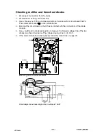
Checking rectifier and freewheel diodes
1. Disconnect the machine from the mains.
2. Dismantle the housing of the machine.
3. Use a Torx key no. T25 to unscrew and remove five screws from circuit board 15AP2.
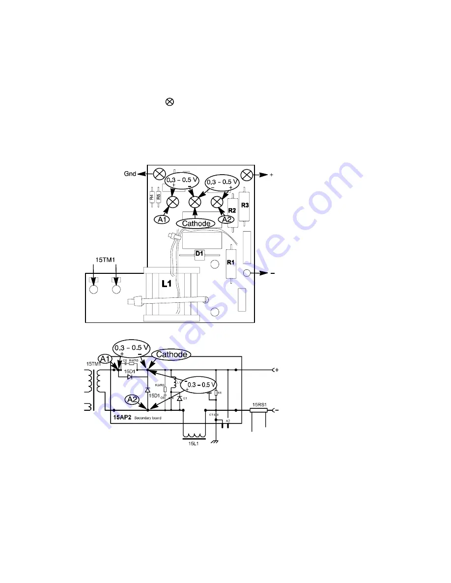
The screws are marked
on the picture below,
4. Bend out the circuit board so that it has no contact with the connections of the diode
module.
5. Use a multimeter in diode test position to measure the forward voltage drop of the two
diodes: see the picture below. The voltage drop must be 0.3 to 0.5 V.
6. If the diode module has to be replaced, follow the instructions on page 23.
Measuring points, circuit board 15AP2
Circuit diagram and measuring points, circuit board 15AP2

