3
B. CONNECTION
1.
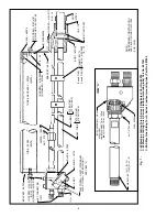
Hoses — Use 3/4 in. cutting oxygen hose with “D”
size fittings, 1/2-in. preheat oxygen and fuel gas
hoses with “C” size fittings. Use 1/4-in. Powder
hose for lengths up to 50-ft., if powder is to be used.
Powder hose should never exceed 50-ft. in length.
NOTE: If new hose is used, use compressed air to
clear hose of dirt, dust, etc.
2.
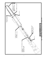
Torch — Attach the preheat oxygen, cutting oxy-
gen and fuel gas hoses to the torch. Attach the
powder hose, when used, to the powder attach-
ment. Make certain all connections are gas-tight.
Attach the desired nozzle to the torch.
III. OPERATION
A. OPERATING PRECAUTIONS
Flow:
There must be proper flow of gases for safe
operation and full performance. This requires the
following three conditions: (1) the regulators that
determine the inlet pressure to the hoses must be set
to the correct pressure: (2) the hoses and their
connectors must have adequate capacity for the job
(hoses that are too long, too small or have connectors
with small passageways can cause problems); and (3)
the throttle valves on the torch must be adjusted with
the procedure shown in these instructions.
Note: Items (1) and (2) can be checked by measuring
the gas pressures at the torch. Gauge adaptors are
available for this purpose.
Backfire:
Improper operation of the torch may cause
the flames to go out with a loud 'pop'. Such a backfire
may be caused by contact of nozzle with the work, by
spatter from the work, by the use of incorrect gas pres-
sures, or by leakage at the cutting nozzle seats due to
dirt or nicks on the seats or to a loose nozzle nut.
Flashback:
Under certain circumstances, the flame
may not 'pop' out (backfire) but instead burn back in-
side the torch with a shrill hissing or squeal. This is
called a 'flashback'. A flashback should never occur if
(1) the equipment is in good condition; (2) preheat ports
on the cutting nozzles or welding tips are cleaned fre-
quently; (3) operating pressures are correct; and (4)
throttle valves are adjusted properly. Should a flash-
back occur, IMMEDIATELY shut off the torch. Allow it
to cool off for at least a minute. Then check your nozzle
or tip, gas pressures, readjust regulator if necessary,
and relight the torch. If flashback recurs, send the cut-
ting torch with nozzle to your distributor for repair.
B. ADJUSTMENT OF CUTTING OXYGEN
PRESSURE
Open the cutting oxygen control valve wide. Turn in
the pressure-adjusting screw on the cutting oxygen
regulator until the pressure gauge on the torch indicates
the correct cutting oxygen pressure. Close the cutting
oxygen valve.
C. ADJUSTMENT OF PREHEAT GAS PRESSURE
Open the throttle valve in the preheat lines. Turn in the
pressure-adjusting screw on the preheat oxygen regu-
lator until the delivery pressure gauge indicates the
correct oxygen pressure. Adjust the fuel gas pressure
the same way, but do not leave the valves open any
longer than necessary. Make sure there are no sparks
or flame near the nozzle flame ports during adjustment
of pressure.
D. ADJUSTMENT OF POWDER DISPENSER,
WHEN USING POWDER
Open the dispenser bleeder valve wide. Adjust the air
regulator to provide approximately 5 psi pressure at
the hopper. Gradually reduce the bleeder valve open-
ing until powder flow from the two outlet tubes on the
powder cutting attachment becomes steady. A slight
adjustment of hopper pressure may be necessary to
obtain the desired powder flow rates. Check the pow-
der flow rate by collecting, in a container, the powder
discharged for 1 minute. If weighing facilities are not
available, a household measuring cup may be used to
approximate the weight of powder discharged. One cup
contains approximately 24 ounces of loosely packed
powder.
E. LIGHTING AND SHUTOFF OF TORCH
Open the preheat oxygen valve a small fraction of a
turn. Open the fuel gas nozzle about 1/4 turn and light
the gas at the nozzle with a friction lighter. Adjust the
flames with the preheat oxygen valve. If the flames are
shorter than desired, open the fuel gas valve and pre-
heat oxygen valve to secure flames of the desired
length. If the flames burn away from the end of the
nozzle, or blow off as soon as lighted, or if the flame
length is greater than desired, close the fuel gas valve
slightly and readjust the preheat oxygen valve.
To shutoff the torch, first close the cutting oxygen valve,
then the fuel gas valve and finally the preheat oxygen
valve. When powder is used, shut off the air supply
Flashbacks can cause serious burns.
Be sure gas flow is sufficient for head or nozzle size.
Adjust regulators for proper psig pressures.
Adjust throttle valves properly.
Keep torch in good repair.
DO NOT
throttle back gasses to use large head or
nozzle on thin material.

